


From plain English to professional, production-ready UML in under 60 seconds — powered by AI and designed for real-world software engineering.
Introduction: The Power of AI-Driven UML Modeling
In modern software development, modeling complex system behaviors is essential — especially for safety-critical applications like Automated Teller Machines (ATMs). Traditionally, creating UML diagrams required deep knowledge of UML syntax, careful layout planning, and significant time investment.
Enter Visual Paradigm All-in-One — a comprehensive desktop and cloud-based modeling platform that integrates professional UML modeling with next-generation AI tools. With this suite, you can generate fully editable, standards-compliant UML State Machine Diagrams directly from plain English descriptions — no drawing skills or coding required.
This article walks you through a real-world case study: modeling the complete state machine logic of an ATM system using Visual Paradigm’s AI-powered features, based on your provided workflow and PlantUML code.
We’ll cover:
-
How to generate the diagram in seconds using AI
-
Refine it with conversational AI editing
-
Manually fine-tune for production use
-
Export and collaborate with team members
By the end, you’ll have a fully traceable, code-generatable, and maintainable ATM state machine diagram — all built with minimal effort and maximum precision.
Prerequisites: Get Ready to Model with AI
Before diving in, ensure you have the right tools:
✅ Download Visual Paradigm Desktop (All-in-One Edition)
👉 https://www.visual-paradigm.com/download/
-
The All-in-One edition includes full AI capabilities (AI Diagram Generation, AI Chatbot, code generation).
-
A free 30-day trial is available. The Community Edition has limited AI features.
✅ Optional but Recommended: Create a Free Visual Paradigm Account
-
Enables cloud sync, OpenDocs integration, and full access to the AI chatbot.
-
Accessible via: https://accounts.visual-paradigm.com
✅ No Coding or Drawing Skills Needed
You don’t need to know UML syntax or be a designer — the AI does the heavy lifting.
Step 1: Generate the Initial Diagram Using AI (30 Seconds)
Visual Paradigm offers two seamless AI entry points. Choose the one that fits your workflow.
Option A: Desktop AI Diagram Generation (Recommended for Projects)
-
Open Visual Paradigm Desktop.
-
Create a new project:
File > New Project→ Select “UML” or “Software Engineering” template. -
Navigate to:
Tools > AI Diagram Generation -
In the AI window:
-
Set Diagram Type:
State Machine Diagram -
Paste the following AI Prompt (crafted from your workflow and PlantUML logic):
-

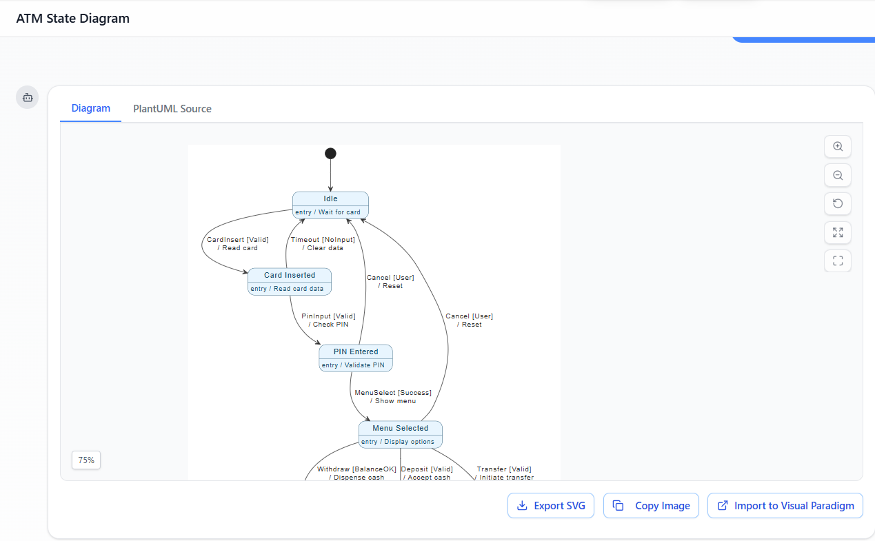
Create a complete UML State Machine Diagram for an Automated Teller Machine (ATM).
Start at Idle (entry: Wait for card).
On event CardInsert [Valid] / Read card → Card Inserted (entry: Read card data).
On event PinInput [Valid] / Check PIN → PIN Entered (entry: Validate PIN).
On event MenuSelect [Success] / Show menu → Menu Selected (entry: Display options).

From Menu Selected:
• Withdraw [BalanceOK] / Dispense cash → Withdrawal (entry: Process withdrawal) → on Complete [Success] / Eject card → Card Ejected.
• Deposit [Valid] / Accept cash → Deposit (entry: Accept cash) → on Complete [Success] / Eject card → Card Ejected.
• Transfer [Valid] / Initiate transfer → Transfer (entry: Initiate transfer) → on Complete [Success] / Eject card → Card Ejected.

Card Ejected (entry: Return card) → back to Idle.

Error paths:
- CardInserted → Idle on Timeout [NoInput] / Clear data
- PIN Entered → Idle on Cancel [User] / Reset
- Menu Selected → Idle on Cancel [User] / Reset

Use blue states with entry actions, label transitions with guards in [brackets] and actions after /, include initial and final pseudostates. Make it clean, professional, and UML-compliant.
-
Click OK.
💡 Result: Within seconds, Visual Paradigm generates a fully editable, native UML state machine diagram — complete with:
-
Correct states and transitions
-
Guards (
[Valid],[BalanceOK], etc.) -
Actions (
/ Read card,/ Dispense cash) -
Entry actions
-
Initial and final pseudostates
-
Clean, modern styling (blue theme)
✅ No image — it’s a real UML diagram that supports code generation, traceability, and editing.
Option B: AI Visual Modeling Chatbot (Great for Quick Iteration)
-
Go to the AI Chatbot:
👉 https://chat.visual-paradigm.com
(Or useTools > Chatbotin the desktop app) -
Start a new chat session and paste the same prompt above.
-
The AI responds with a visual representation of the diagram.
-
Click “Import to Visual Paradigm” or “Open in Editor” to load it into your desktop project.
🎯 Advantage: Ideal for rapid prototyping, testing variations, or when you’re iterating quickly.
Step 2: Refine & Enhance with AI Chat (Conversational Editing)
Stay in the same chat session (or open the diagram and use Tools > Chatbot) and type follow-up instructions like:
“Add entry actions to every state exactly as described: Idle = Wait for card, Card Inserted = Read card data, etc.”
“Group Withdrawal, Deposit, and Transfer into a composite state with a history pseudostate.”
“Check for unreachable states or missing guards and fix them.”
“Generate Java code from this state machine.”
“Add a note explaining the [BalanceOK] guard condition.”
🧠 The AI responds in real time, either:
-
Updating the diagram live (if supported)
-
Returning revised PlantUML-like text you can re-import
-
Suggesting improvements based on UML best practices
🔄 Iterative Design Made Easy: Change requirements? Just ask.
Example:
“Add a new state for ‘Card Invalid’ after CardInsert fails.”
→ AI adds it with proper transitions and guards.
This is true AI-first modeling: you describe behavior, and the AI helps you refine it into a robust, maintainable design.
Step 3: Manual Fine-Tuning in the Visual Paradigm Editor (Full Control)
Even though the AI generates a solid foundation, manual refinement ensures perfection for production use.
✅ Edit States & Actions
-
Double-click any state → Edit:
-
Name (e.g.,
Withdrawal) -
Entry action:
entry / Process withdrawal -
Exit action:
exit / Log transaction
-
✅ Customize Transitions
-
Right-click a transition → Edit:
-
Change event:
Withdraw→WithdrawCash -
Add or modify guard:
[BalanceOK]→[BalanceOK && IsAccountActive] -
Update action:
/ Dispense cash→/ Dispense cash, update balance
-
✅ Add Advanced UML Constructs
Use the toolbar to enhance your diagram:
-
Initial Pseudostate: Black circle at start
-
Final State: Bull’s-eye at end
-
Composite States: Wrap
Withdrawal,Deposit,Transferinto a single composite state (e.g.,Transaction Process)-
Add history pseudostate (
H) to resume previous substate after cancellation
-
-
Orthogonal Regions (optional): Model concurrent behaviors like “Card Inserted” vs. “Network Connected”
✅ Apply Styling & Layout
-
Right-click diagram → Styles → Choose a modern theme (e.g., Blue Modern)
-
Use Auto Layout (
Diagram > Layout > Auto Layout) to fix alignment and spacing
✅ Validate Your Diagram
-
Right-click diagram → Verify
-
The tool checks for:
-
Missing initial/final states
-
Unreachable states
-
Invalid syntax (e.g., missing guards)
-
Inconsistent actions or events
-
✅ Fix any issues flagged — your diagram is now UML-compliant and production-ready.
Step 4: Optional – Import Your Original PlantUML Code (Advanced Users)
If you already have a PlantUML version of your ATM state machine, you can import it directly.
🔧 Method: Use the PlantUML-VP Plugin
-
Install the free PlantUML-VP-Plugin:
-
Follow installation instructions for Visual Paradigm Desktop
-
Open your
.pumlfile in the plugin. -
Click “Convert to Visual Paradigm Diagram”.
-
The AI re-creates your diagram with:
-
Improved layout
-
Native UML structure
-
Full editability
-
💡 Or, paste your entire PlantUML code into the AI Chatbot and say:
“Convert this PlantUML state machine to a native Visual Paradigm diagram and improve layout.”
The AI will return a polished, professional version — no manual rework needed.
Step 5: Validation, Documentation & Export
Now that your diagram is complete, it’s time to validate, document, and share.
✅ Validation
-
Use
Verifyto ensure UML correctness. -
Cross-check with use cases (e.g., “Withdraw Cash” use case should map to the
Withdrawalstate).
✅ Generate Documentation
-
Go to:
Diagram > Generate Documentation -
Choose format: HTML, PDF, or Word
-
Include:
-
Diagram description
-
State definitions
-
Transition logic
-
Entry/exit actions
-
Guard conditions
-
📄 Output: A professional report ready for stakeholders, auditors, or developers.
✅ Export Options
| Format | Use Case |
|---|---|
| PNG/SVG/PDF | Presentations, reports, documentation |
| HTML Web Report | Share online with team or clients |
| Java / Python / C++ Code | Generate state machine classes automatically |
| Model Export (XMI) | Integrate with other tools (e.g., databases, test frameworks) |
🚀 Code Generation Example (Java):
After generating code, you get a class likeATMStateMachine.javawith:
State enum
Transition handlers
Guard logic (
if (balance >= amount))Entry/exit methods
This enables direct integration into your application.
Step 6: Save & Collaborate
💾 Save Your Project
-
Save as
.vppfile (Visual Paradigm Project) -
Use version control (e.g., Git) for project history
🌐 Share & Collaborate
-
Upload to Visual Paradigm Online or Teamwork Cloud
-
Invite team members to view, comment, or edit in real time
-
Use OpenDocs to link this diagram to:
-
Use case diagrams
-
Class diagrams
-
Requirements documents
-
Test cases
-
🔁 Future Iterations:
“Improve this ATM diagram with error handling for invalid card”
→ AI updates the diagram with new states, guards, and transitions.
Benefits of This AI-First Approach
| Benefit | Description |
|---|---|
| Speed | From idea to diagram in under 60 seconds |
| Accuracy | AI ensures perfect UML syntax — no human errors |
| Iterative Design | Change requirements? Just chat with AI |
| Full Editability | Native UML — not an image |
| Code Generation | Automatically generate Java/Python/C++ state machines |
| Traceability | Link to use cases, classes, and requirements |
| Enterprise-Ready | Supports large-scale, team-based modeling |
Next Steps: Expand Your ATM System Model
You’ve now built a robust, AI-powered UML State Machine Diagram for an ATM. But the journey doesn’t stop here.
Would you like me to help you with:
🔹 Generate Java or Python code from this diagram?
🔹 Create a Sequence Diagram showing the interaction between ATM, Card Reader, Bank Server, and User?
🔹 Model concurrent behaviors (e.g., network status vs. transaction flow) using orthogonal regions?
🔹 Add security features like session timeouts, lockout after 3 failed PIN attempts?
👉 Just say the word — I’ll provide the exact prompts, code, and diagrams to take your ATM system to the next level.
Conclusion: The Future of UML Modeling is AI-Powered
With Visual Paradigm All-in-One, you’re no longer limited by drawing skills or UML complexity.
You can now:
-
Describe behavior in plain English
-
Let AI generate accurate, standards-compliant UML diagrams
-
Refine them interactively
-
Export to code, documentation, or collaboration platforms
This AI-first workflow transforms how teams design, validate, and deliver complex systems — from ATMs to IoT devices, banking apps, and beyond.
✅ Ready to Get Started?
👉 Download Visual Paradigm All-in-One now:
🔗 https://www.visual-paradigm.com/download/
💡 Pro Tip: Bookmark this guide and use it as your AI-UML onboarding kit for every new project.
📣 Final Thought:
The future of software design isn’t just about writing code — it’s about thinking clearly, modeling precisely, and iterating fast.
With Visual Paradigm and AI, you’re not just building diagrams.
You’re building better systems, faster.
Need a downloadable version of this guide?
Let me know — I’ll generate a PDF, Markdown, or HTML version for your team or documentation portal.
Happy modeling! 🚀
Resource
- State Diagrams – Visual Paradigm: A comprehensive overview of UML state diagrams, explaining their purpose, components, and best practices for modeling system behavior over time.
- AI Diagram Generator – Visual Paradigm Updates: A release announcement detailing the integration of AI-powered diagram generation in Visual Paradigm, enabling faster creation of UML and other diagrams, including state machines.
- AI-Powered UML State Machine Diagram Generator – Visual Paradigm Chat: A feature guide demonstrating how to use Visual Paradigm’s AI chatbot to generate UML state machine diagrams from natural language descriptions.
- Beginner’s Guide to State Machine Diagrams – Visual Paradigm Blog: A beginner-friendly tutorial that walks through the fundamentals of creating and interpreting state machine diagrams using UML.
- Comprehensive Guide to UML State Machine Diagrams – Archimetric: A detailed guide that combines theoretical knowledge with practical examples using Visual Paradigm and AI tools to design robust state machine diagrams.
- State Machine Diagram Tutorial – Visual Paradigm Online: An interactive, step-by-step tutorial for creating state machine diagrams online, ideal for users new to UML modeling.
- UML State Diagram Gallery – Visual Paradigm: A collection of real-world examples and templates of UML state diagrams, showcasing various applications and design patterns.
- Comprehensive Guide to UML State Machine Diagrams – Archimetric (Revisited): A repeat reference emphasizing the integration of AI and UML modeling in engineering systems, particularly in domains like automation and control systems.
- AI Chatbot Feature – Visual Paradigm: A description of Visual Paradigm’s AI chatbot, which assists users in generating diagrams, writing specifications, and understanding modeling concepts through natural language interaction.
- Mastering State Diagrams with Visual Paradigm AI – Cybermedian: A practical case study illustrating how AI-enhanced state diagrams are used in designing an automated toll system, demonstrating real-world application.
- AI-Powered UML State Machine Diagram Generator – Visual Paradigm Chat (Revisited): A second reference to the same AI diagram generation tool, reinforcing its utility in rapidly prototyping and refining state machine models.
- AI Diagram Generator – Visual Paradigm Updates (Revisited): A repeat of the AI release note, underscoring the significance of AI in accelerating diagram creation and improving modeling accuracy.
- AI Chatbot Feature – Visual Paradigm (Revisited): A repeated entry highlighting the ongoing importance of AI integration in diagramming workflows.
- YouTube Tutorial: UML State Machine Diagrams: A video tutorial that visually demonstrates the creation and interpretation of UML state machine diagrams, offering a dynamic learning experience for visual learners.