
This guide provides a structured, step-by-step approach to transforming user requirements—expressed through use case scenarios—into a detailed technical design using class diagrams. It emphasizes the synergy between functional requirements and system architecture, ensuring that the final software design is both aligned with user needs and technically robust.
🔹 Introduction: The Role of Use Cases and Class Diagrams
In object-oriented software development, use case diagrams and class diagrams serve complementary roles:
- Use Case Diagrams define what the system does — capturing functional requirements from the user’s perspective.
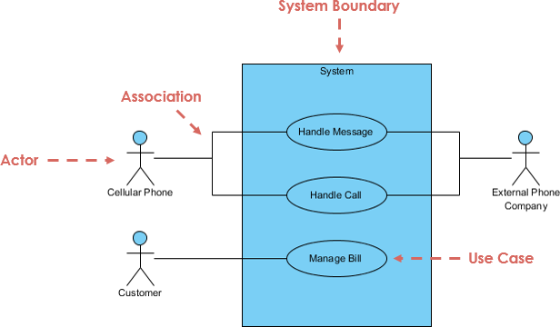
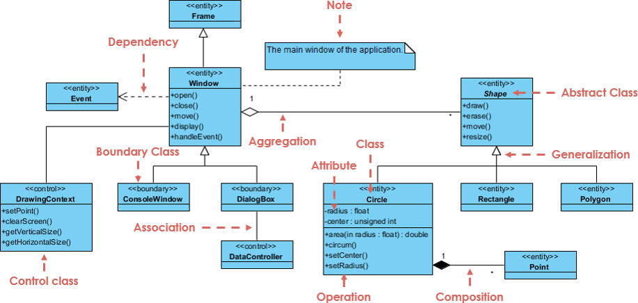
- Class Diagrams define how the system is structured — detailing the static components (classes, attributes, methods, relationships) that implement those functions.
✅ Key Insight: Use cases describe behavior; class diagrams model structure. Together, they form the foundation of a well-designed system.
🔹 Core Relationship: Use Case → Class Diagram
| Aspect | Use Case Diagram | Class Diagram |
|---|---|---|
| Focus | Behavior, interaction, actors | Structure, objects, data |
| Purpose | Define system functionality | Define implementation architecture |
| Viewpoint | User-centric (external view) | Developer-centric (internal view) |
🔄 Evolution of Design
- Use Case → Defines the goal (e.g., “Customer places an order”).
- Class Diagram → Defines the components needed to fulfill that goal.
- Sequence Diagram → Acts as a bridge, showing how objects interact to execute the use case.

💡 Best Practice: Never design class diagrams in isolation. Always trace them back to use cases.
🔹 Step-by-Step Process: From Use Case to Class Diagram
✅ Step 1: Define the Scope with Use Cases
Start by identifying:
- Actors (users or external systems interacting with the system)
- Use Case Goals (what the actor wants to achieve)
Example:
Actor: Customer
Use Case: Place Order
Goal: Customer selects products, reviews cart, and submits an order.
📌 This defines the scope and context for your class diagram.
✅ Step 2: Identify Domain Entities via Noun/Verb Analysis
Analyze the use case text to extract potential classes and methods.
🔹 Noun Analysis → Potential Classes
Look for nouns that represent real-world entities or data objects.
| Noun | Likely Class Type |
|---|---|
| Customer | Entity Class |
| Order | Entity Class |
| Product | Entity Class |
| Cart | Entity or Control Class |
| Invoice | Entity Class |
| Payment | Control or Entity Class |
✅ Tip: Focus on persistent, long-lived data objects — these are typically Entity Classes.
🔹 Verb Analysis → Potential Methods
Look for verbs that represent actions or behaviors.
| Verb | Likely Method |
|---|---|
| Place order | placeOrder() |
| Calculate total | calculateTotal() |
| Add to cart | addToCart() |
| Validate payment | validatePayment() |
| Generate invoice | generateInvoice() |
✅ Tip: Verbs often become methods within classes, especially in control and boundary classes.
✅ Step 3: Apply the Entity-Control-Boundary (ECB) Pattern
The ECB model is a proven strategy to categorize classes derived from use cases.
| Class Type | Role | Example |
|---|---|---|
| Boundary | Interface between actor and system | OrderFormUI, LoginScreen, PaymentGatewayUI |
| Control | Manages the logic and flow of a use case | OrderProcessor, AuthenticationManager, CheckoutController |
| Entity | Represents persistent data or business concepts | Customer, Order, Product, Invoice |
🛠️ How to Apply ECB:
- For each use case, identify one or more Control classes to manage the workflow.
- Identify Boundary classes for user interaction points.
- Identify Entity classes for core data.
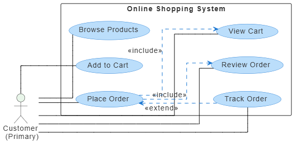
📌 Example: In “Place Order” use case:
- Boundary:
OrderFormUI - Control:
OrderPlacementService - Entity:
Customer,Order,Product,Cart
✅ Step 4: Create an Initial Class Diagram
Based on the ECB analysis and noun/verb extraction, sketch a preliminary class diagram.
Include:
- Classes (with name, attributes, methods)
- Relationships: associations, aggregations, compositions
- Multiplicity (e.g., 1..*, 0..1)
Example (Simplified):

PlantUML Class diagram Code: (generated by Visual Paradigm AI Chatbot)
@startuml

skinparam {
roundcorner 8
ArrowColor #444444
ArrowFontColor #444444
BorderColor #444444

Class {
BorderColor #1A237E
BackgroundColor #E8EAF6
FontColor #1A237E
}

Interface {
BorderColor #A7C5C5
BackgroundColor #E0F2F1
FontColor #444444
}

Package {
BorderColor #6D876D
BackgroundColor #E6F0E6
FontColor #3D553D
}
}

package "E-Commerce System" {
class "Customer" {
-id : String
-name : String
-email : String
+placeOrder() : Order
+viewOrder(order : Order)
}

class "Product" {
-productId : String
-name : String
-price : Double
}

class "Cart" {
-items : List<Product>
+addItem(product : Product)
+removeItem(product : Product)
+getTotal() : Double
}

class "Order" {
-orderId : String
-date : Date
-items : List<Product>
+placeOrder() : Boolean
+calculateTotal() : Double
+getTotal() : Double
}
}

' Relationships

Customer --|> Order : creates
Customer --> Cart : manages
Cart *-- "many" Product : contains
Order *-- "many" Product : contains
Cart --> Order : used to create

' Add dependency
Order ..> Cart : depends on
Order ..> Product : references

' Aggregation: Order aggregates items from Cart
Cart o-- Order : forms basis for

hide class circle

@enduml✅ Note: This is just the starting point. Refinement comes next.
✅ Step 5: Use Sequence Diagrams as a Bridge
To refine the class diagram, create a sequence diagram for each major use case.
Why?
- Shows object interactions over time.
- Reveals missing classes, incorrect responsibilities, or flawed relationships.
- Helps validate that the class diagram supports the required behavior.
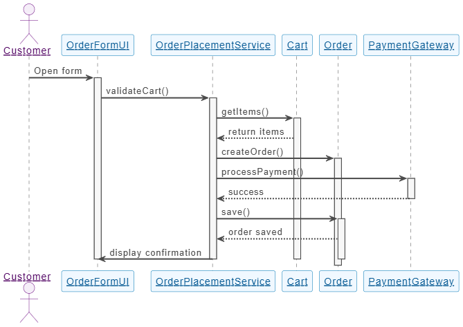
Example: Sequence Diagram for “Place Order”
@startuml

skinparam sequenceParticipant underline
skinparam {
' Overall style
FontSize 14

' Colors
ArrowColor #4A4A4A
ArrowFontColor #4A4A4A
BackgroundColor #FFFFFF
BorderColor #DEDEDE
FontColor #333333

' Participant styling
Participant {
BorderColor #0077B6
BackgroundColor #F0F8FF
FontColor #005691
}

' Actor styling
Actor {
BorderColor #6A057F
BackgroundColor #F5EEF8
FontColor #510363
}

' Sequence specific
Sequence {
ArrowThickness 2
LifeLineBorderColor #444444
LifeLineBackgroundColor #F7F7F7
BoxBorderColor #AAAAAA
BoxBackgroundColor #FFFFFF
BoxFontColor #333333
}
}

actor "Customer" as CUS
participant "OrderFormUI" as UI
participant "OrderPlacementService" as OPS
participant "Cart" as CART
participant "Order" as ORD
participant "PaymentGateway" as PG

CUS -> UI: Open form
activate UI

UI -> OPS: validateCart()
activate OPS

OPS -> CART: getItems()
activate CART
CART --> OPS: return items

OPS -> ORD: createOrder()
activate ORD

OPS -> PG: processPayment()
activate PG

PG --> OPS: success
deactivate PG

OPS -> ORD: save()
activate ORD
ORD --> OPS: order saved

OPS -> UI: display confirmation
deactivate ORD
deactivate OPS
deactivate CART
deactivate UI

@enduml🔍 Insights Gained:
- Need a
PaymentGatewayclass → Add as Boundary or Entity. OrderPlacementServicemay need to handle exceptions → AddExceptionHandlinglogic.Cartmay need to notifyOrderwhen items change → Add association.
✅ Update the class diagram based on insights from the sequence diagram.
✅ Step 6: Refine the Class Diagram
Enhance the initial diagram with:
- Attributes (data fields) from use case details
- Methods (operations) from verbs and sequence flows
- Relationships:
- Association: General link (e.g., Customer ↔ Order)
- Aggregation: “Has-a” relationship (e.g., Order has a Cart)
- Composition: Strong ownership (e.g., Order contains OrderItems)
- Inheritance: Generalization (e.g.,
PremiumCustomerinherits fromCustomer)
- Multiplicity (1, 0..1, 1..*, etc.)
📌 Refinement Example:
- Add
OrderItemclass as composition ofOrder. - Add
Paymentclass as aggregation ofOrder. - Add
validate()method toOrderclass. - Specify that
Orderhas oneCustomerand manyOrderItems.
✅ Step 7: Finalize and Validate the Class Diagram
Before implementation:
- Review against all use cases.
- Ensure every use case can be fulfilled by object interactions.
- Check for:
- Redundant classes
- Missing responsibilities
- Incorrect inheritance or multiplicity
- Use UML tools (e.g., Visual Paradigm) for consistency and documentation.
✅ Validation Tip: Ask: “Can I walk through every use case using only the classes and relationships in this diagram?”
✅ Step 8: Use the Class Diagram for Implementation
The finalized class diagram becomes the blueprint for coding.
How to Use It:
- Generate code skeletons (classes, methods, attributes).
- Define interfaces and data types.
- Guide team collaboration — all developers refer to the same model.
- Support code reviews and documentation.
📌 Example Output (Pseudocode):
public class Order {
    private String orderId;
    private Date date;
    private Customer customer;
    private List<OrderItem> items;

    public void placeOrder() { ... }
    public double calculateTotal() { ... }
    public void save() { ... }
}
🔹 Best Practices Summary
| Practice | Why It Matters |
|---|---|
| Always start with use cases | Ensures design meets real user needs |
| Use ECB for class categorization | Prevents design chaos; promotes separation of concerns |
| Use sequence diagrams as a bridge | Connects behavior (use case) to structure (class diagram) |
| Iterate and refine | Class diagrams evolve as use cases become clearer |
| Validate with multiple use cases | Ensures completeness and consistency |
| Use UML tools | Improves clarity, collaboration, and maintainability |
🔹 Common Pitfalls to Avoid
| Pitfall | Solution |
|---|---|
| Creating classes without use case justification | Every class should map to a use case or domain concept |
| Overloading control classes | Split complex logic into multiple control classes |
| Ignoring multiplicity and relationships | They define real-world constraints and data integrity |
| Forgetting boundary classes | Without them, the system has no user interface layer |
| Treating all nouns as classes | Only include relevant, persistent domain entities |
🔹 Conclusion: The Power of Integration
✅ Use cases tell us what the system must do.
✅ Class diagrams tell us how it will do it.
By systematically refining class diagrams from use case scenarios using the ECB model, noun/verb analysis, and sequence diagrams as a bridge, you ensure that:
- The design is user-driven and requirements-focused.
- The architecture is modular, maintainable, and scalable.
- Development teams have a shared understanding of the system.
This integrated approach is foundational to successful object-oriented analysis and design (OOAD) and remains a cornerstone of modern software engineering practices.
🔹 References & Further Reading
- Grady Booch, Object-Oriented Analysis and Design with Applications
- James Rumbaugh, Ivar Jacobson, Grady Booch – The Unified Modeling Language Reference Manual
- Martin Fowler – UML Distilled: A Brief Guide to the Standard Object Modeling Language
- Craig Larman – Applying UML and Patterns: An Introduction to Object-Oriented Analysis and Design
- IEEE Std 830-1998 – IEEE Recommended Practice for Software Requirements Specifications
📘 Final Tip: Keep your class diagrams living documents. Update them as requirements evolve — they’re not just a design artifact, but a shared source of truth throughout the development lifecycle.
✅ You now have a complete, actionable guide to turning user needs into technical design.
Use it confidently in your next project.
Resource
- What Is a Use Case Diagram? – A Complete Guide to UML Modeling: This in-depth explanation covers the purpose, components, and best practices for software requirements modeling.
- What Is a Class Diagram? – A Beginner’s Guide to UML Modeling: An informative overview detailing the purpose, components, and importance of class diagrams in software development and system design.
- What Is a Sequence Diagram? – A UML Guide: This guide explains how sequence diagrams visualize object interactions over time within software systems.
- Visual Paradigm – Use Case Description Features: This resource highlights tools designed to help software teams document user interactions and system behavior with precision.
- AI-Powered UML Class Diagram Generator by Visual Paradigm: An advanced tool that automatically generates UML class diagrams from natural language descriptions.
- AI-Powered Sequence Diagram Refinement Tool | Visual Paradigm: This feature highlight explains how AI enhances software design by automatically improving and optimizing sequence diagrams with intelligent suggestions.
- AI Use Case Description Generator by Visual Paradigm: This tool utilizes AI to automatically generate detailed use case descriptions from user inputs, significantly accelerating system analysis and documentation.
- Comprehensive Guide to Sequence Diagrams in Software Design: A detailed handbook section explaining the structure and best practices for using sequence diagrams to model dynamic behavior.
- Learning Class Diagrams with Visual Paradigm – ArchiMetric: This article describes how Visual Paradigm provides an easy-to-use platform for creating and managing class diagrams.
-
Automating Use Case Development with AI in Visual Paradigm: This resource explores how AI-powered generators improve consistency and reduce manual effort in use case development.