
In the rapidly evolving world of digital commerce, building scalable, maintainable, and robust e-commerce platforms is both a challenge and an opportunity. One of the most effective ways to achieve this is through structured architectural modeling using Unified Modeling Language (UML). This article presents a comprehensive case study on designing an e-commerce system using the Boundary-Control-Entity (BCE) architectural pattern, supported by key UML concepts such as generalization, composition, aggregation, and dependency. The result is a clean, modular, and future-proof system architecture that aligns with industry best practices.
1. Architectural Overview: A Modular Foundation for E-Commerce
At its core, the e-commerce system is designed around three fundamental layers—Boundary, Control, and Entity—each with a distinct responsibility. This separation ensures that changes in one layer do not ripple uncontrollably into others, promoting maintainability, testability, and scalability.
Core Components of the BCE Architecture
| Component Type | Role in the System | Example Classes |
|---|---|---|
| Entity Classes | Represent persistent data that survives beyond a session. They model business objects and their state. | Product, ShoppingCart, CommerceSystem |
| Boundary Classes | Serve as interfaces between external actors (users, devices, APIs) and the system. They handle input/output and user interaction. | WebFrontend, MobileFrontend, ConsoleWindow |
| Control Classes | Act as the “brain” of the system. They coordinate logic between boundaries and entities, manage workflows, and enforce business rules. | SystemEventManager, DataSyncManager |
This layered approach ensures that:
- The UI (Boundary) remains decoupled from data structures (Entity).
- Business logic is centralized and reusable (Control).
- The system can evolve without breaking existing components.
✅ Why BCE?
The BCE pattern is particularly well-suited for interactive systems like e-commerce platforms. It naturally separates concerns, making it easier to:
- Add new frontends (e.g., voice interface or IoT devices)
- Modify business logic without touching the UI
- Scale individual components independently
2. Core UML Concepts in Action: Building a Robust Model
To translate the BCE architecture into a precise, visual blueprint, several UML relationship types are applied strategically. These relationships define how classes interact and depend on one another, forming the backbone of the system’s structure.
Key UML Relationships and Their Applications
| UML Concept | Application in the Case Study | Why It Matters |
|---|---|---|
| Generalization (Inheritance) | PaymentProcessor is an abstract class; concrete implementations like PayPalPayment and BankTransferPayment inherit from it. |
Enables open/closed principle: the system is closed for modification but open for extension. Adding new payment methods doesn’t require changing existing code. |
| Composition (Strong “Part-of” Relationship) | ShoppingCart contains Product entries via a black diamond (●). A cart cannot exist without its items, and items are destroyed when the cart is. |
Ensures data integrity and lifecycle consistency. Prevents orphaned product entries. |
| Aggregation (Weak “Has-a” Relationship) | ECommerceApplication has an ShoppingCart (white diamond ◯). The cart can exist independently of the application instance. |
Supports reusability and flexibility. Multiple applications can share a single cart instance. |
| Dependency (Dashed Arrow) | ECommerceApplication depends on SystemEventManager (dashed line with arrow). The application uses the manager but doesn’t own it. |
Reduces coupling. The application doesn’t need to know the internal details of the event manager. |
💡 Visual Insight:
In a UML class diagram, these relationships appear as:
- Solid line with triangle → Generalization (inheritance)
- Black diamond on the container side → Composition
- White diamond on the container side → Aggregation
- Dashed line with arrow → Dependency
These visual cues make the model intuitive for developers, architects, and stakeholders alike.
3. Design Principles & Best Practices: Engineering for Excellence
A well-designed system isn’t just about functionality—it’s about long-term sustainability. The following best practices were rigorously applied during the modeling phase:
✅ 1. Separation of Concerns (BCE Pattern)
One of the most critical design rules: no direct communication between Boundary and Entity classes.
- ❌ Bad:
WebFrontenddirectly accessesProductattributes. - ✅ Good:
WebFrontend→SystemEventManager→Product
This ensures:
- UI changes don’t affect data models.
- Business logic remains centralized and testable.
- The system is resistant to “spaghetti code.”
✅ 2. Stereotyping for Clarity
Using UML stereotypes (<<boundary>>, <<control>>, <<entity>>) makes the diagram self-documenting.
<<boundary>> WebFrontend→ Clearly identifies it as a user interface.<<control>> SystemEventManager→ Signals it manages system-wide logic.<<entity>> Product→ Indicates persistent data.
🎯 Benefit: Non-technical stakeholders (product managers, QA teams) can understand the diagram without deep technical knowledge.
✅ 3. Multiplicity: Enforcing Business Rules
Multiplicity (e.g., 1..*, 0..1, *) defines the number of instances involved in a relationship.
ShoppingCart—1—*—Product: One cart holds many products.Product—1—*—ShoppingCart: A product can be in many carts (but each line item is unique to one cart).
These constraints reflect real-world business rules and prevent invalid data states.
✅ 4. Encapsulation: Hiding Internal State
All attributes are marked with - (private), and operations with + (public).
PlantUML Class
@startuml

class ShoppingCart {
- cartID: String
- items: List<Product>
--
+ addItem(p: Product)
+ removeItem(p: Product)
+ calculateTotal(): double
}

@enduml🔐 Why it matters:
The internal state (cartID, items) is hidden. Only public methods (calculateTotal()) are exposed, ensuring data consistency and preventing unauthorized access.
4. Implementation Workflow: From Idea to Diagram
Building a solid architectural model isn’t arbitrary—it follows a proven, repeatable workflow. Here’s how the e-commerce system was developed step-by-step:
Step 1: Identify Entities (The “Nouns” of the Business)
Start by listing core business objects:
Product(name, price, stock)ShoppingCart(items, total, user ID)Order(status, date, payment info)User(credentials, preferences)
🧠 Tip: Ask: “What data persists beyond a user session?”
Step 2: Define Boundaries (How Users Interact)
Identify all external access points:
WebFrontend(browser-based UI)MobileFrontend(iOS/Android app)ConsoleWindow(admin tool for debugging or inventory management)
📱 Bonus: This design allows easy expansion to future interfaces (e.g., smartwatch, voice assistant).
Step 3: Insert Control Classes (The “Verbs” of the System)
Create classes that orchestrate logic between boundaries and entities:
SystemEventManager: Handles user actions (e.g., “Add to Cart”, “Checkout”).DataSyncManager: Ensures data consistency across sessions and devices.PaymentProcessor: Abstract base for payment logic.
⚙️ Key Insight: Control classes are where business rules live—e.g., “Apply discount if cart total > $100.”
Step 4: Establish Relationships
Use UML to define how classes connect:
- Use composition for tightly coupled parts (e.g., cart items).
- Use aggregation for loosely related components (e.g., app and cart).
- Use dependency for services the system uses but doesn’t own.
🔄 Iterate: Refine the diagram through feedback from developers and product teams.
 Pattern")
5. Next Step: Sequence Diagram for the “Checkout” Process
Would you like a Sequence Diagram that visualizes the checkout flow based on this class structure?
Here’s what it would show:
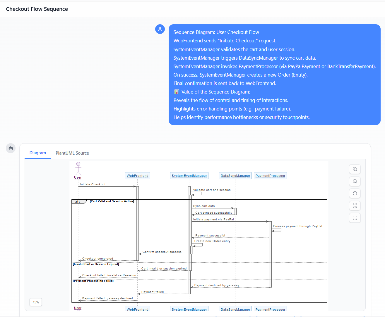
Sequence Diagram: User Checkout Flow
WebFrontendsends “Initiate Checkout” request.SystemEventManagervalidates the cart and user session.SystemEventManagertriggersDataSyncManagerto sync cart data.SystemEventManagerinvokesPaymentProcessor(viaPayPalPaymentorBankTransferPayment).- On success,
SystemEventManagercreates a newOrder(Entity). - Final confirmation is sent back to
WebFrontend.
📊 Value of the Sequence Diagram:
- Reveals the flow of control and timing of interactions.
- Highlights error handling points (e.g., payment failure).
- Helps identify performance bottlenecks or security touchpoints.
- Generated by Visual Paradigm AI Chatbot
Conclusion: Building Systems That Scale
This case study demonstrates how UML modeling, combined with the BCE architectural pattern, provides a powerful framework for designing modern e-commerce systems. By applying core UML concepts—generalization, composition, aggregation, and dependency—alongside proven design principles like encapsulation and separation of concerns, we create systems that are:
- ✅ Maintainable (easy to update and debug)
- ✅ Extensible (new features can be added without breaking existing code)
- ✅ Testable (each layer can be unit tested independently)
- ✅ Collaborative (clear communication between developers, product teams, and stakeholders)
🏁 Final Thought:
A well-crafted UML class diagram is not just documentation—it’s a living blueprint that guides development, prevents architectural debt, and ensures your e-commerce platform can grow with your business.
🔗 Next Steps
Would you like me to:
- Generate a PlantUML code snippet for the class diagram?
- Create a Sequence Diagram for the “Checkout” process?
- Export this model into a diagram file (e.g., .puml, .svg, .png)?
Let me know—happy to help bring your e-commerce architecture to life! 🚀
Resource
- AI-Powered UML Class Diagram Generator by Visual Paradigm: This tool automatically generates UML class diagrams directly from natural language descriptions. It is designed to significantly streamline the software design and modeling process.
- From Problem Description to Class Diagram: AI-Powered Textual Analysis: This article explores how Visual Paradigm uses AI to convert natural language problem descriptions into accurate class diagrams. It focuses on transforming unstructured text into structured software models.
- AI Use Case Description Generator by Visual Paradigm: This AI-powered tool automatically generates detailed use case descriptions based on user inputs. It is a specialized solution for accelerating system analysis and formal documentation.
- Automating Use Case Development with AI in Visual Paradigm: This resource details how AI-powered generators reduce manual effort and improve consistency during the development of use cases. It highlights how AI enhances the efficiency of UML modeling workflows.
- Real-Life Case Study: Generating UML Class Diagrams with Visual Paradigm AI: This study showcases how an AI assistant successfully transformed textual requirements into accurate class diagrams for a real-world project. It provides a practical look at the accuracy of AI in software engineering.
- Textual Analysis in Visual Paradigm: From Text to Diagram: This official guide explains how the textual analysis feature transforms written descriptions into structured diagrams like class and use case diagrams. It is an essential resource for those looking to automate their modeling process.
- Revolutionizing Use Case Elaboration with Visual Paradigm AI: This guide explains how AI-driven tools enhance use case modeling by automating the elaboration process. It focuses on improving the clarity and detail of software requirements.
- Streamlining Class Diagrams with Visual Paradigm’s AI: This article details how AI-powered tools reduce the complexity and time required to build accurate models for software projects. It highlights the role of AI in maintaining design precision.
- Visual Paradigm Use Case Description Generator Tutorial: This step-by-step tutorial teaches users how to automatically produce detailed use case documents from their visual diagrams. It bridges the gap between visual design and written specifications.
- Comprehensive Tutorial: Generate UML Class Diagrams with Visual Paradigm’s AI Assistant: This tutorial demonstrates how to use a specialized AI assistant to create precise UML class diagrams from plain text input. It provides a clear walkthrough for users adopting intelligent modeling tools.
