


In today’s dynamic and competitive business environment, efficient Order-to-Delivery (O2D) processes are critical to customer satisfaction, operational agility, and supply chain resilience. This article presents a detailed analysis of a complex Order-to-Delivery workflow modeled using BPMN (Business Process Model and Notation), highlighting how a manufacturer manages inventory constraints through strategic procurement and external auctions.
Through the lens of a real-world case study, we explore the interplay between stakeholders—Customers, Manufacturers, Suppliers, and Bidders—and examine how decision logic, message flows, and subprocess orchestration ensure continuity in fulfillment despite supply chain volatility.
1. Process Overview: From Order Request to Delivery
The lifecycle of an order begins when a Customer submits an Order Request to the Manufacturer. This triggers a sequence of checks and actions designed to determine whether the order can be fulfilled within operational constraints.
The core challenge lies in balancing production capacity with part availability. The manufacturer cannot deliver unless both are met. To address this, the process incorporates dynamic decision-making and external collaboration mechanisms, including supplier coordination and part auctions.
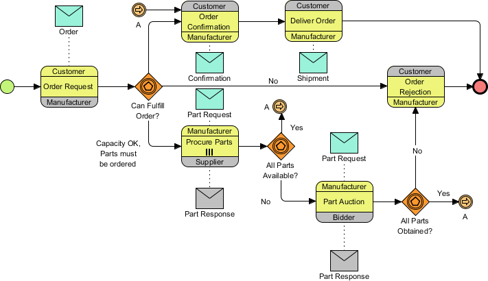
✅ Key Insight: The process is not linear—it branches based on real-time data, allowing the organization to adapt to shortages without abandoning orders entirely.
2. Decision Logic: The Three Critical Gateways
At the heart of the process are three exclusive gateways, each representing a pivotal decision point. These gateways guide the flow based on data-driven conditions.
Gate 2.1: Can Fulfill Order?
This gateway evaluates the manufacturer’s current ability to fulfill the order.
-
Yes (Direct Path): If both production capacity and required parts are available, the process proceeds directly to Order Confirmation.
-
No (Procurement Path): If capacity is sufficient but parts are missing, the system initiates the “Procure Parts” subprocess.
-
Reject (Rejection Path): If the manufacturer lacks both capacity and parts, the order is rejected immediately to avoid resource waste.
📌 Strategic Implication: This gate ensures that only feasible orders move forward, reducing downstream risks and improving planning accuracy.
Gate 2.2: All Parts Available?
After initiating procurement, the manufacturer contacts the Supplier to request missing parts. The response determines the next step.
-
Yes: All parts have been secured → flow continues to the final fulfillment check.
-
No: Some parts remain unavailable → the process escalates to a Part Auction.
🔄 Why Auctions? When suppliers cannot meet demand, the manufacturer turns to a competitive bidding system to source parts from third-party bidders—ensuring availability even under supply chain stress.
Gate 2.3: All Parts Obtained?
This final checkpoint occurs after the auction concludes.
-
Yes: All required parts have been acquired → the process returns to the main flow via Link Event “A”.
-
No: Despite the auction, parts are still missing → the order is rejected due to unfulfillable conditions.
⚠️ Critical Note: Even after investing in auctions, failure to secure parts results in rejection—emphasizing the importance of supplier reliability and auction design.
3. Stakeholder Interaction: Choreography in Action
The diagram uses Choreography Tasks (three-banded boxes) to visually represent collaborative interactions between entities. This is a key BPMN feature for modeling multi-organizational processes.
Each choreography task consists of:
| Band | Purpose | Example |
|---|---|---|
| Top Band | Initiator of the interaction | Manufacturer sends a request |
| Middle Band | Name of the activity | Request Parts from Supplier |
| Bottom Band | Recipient or partner | Supplier receives the request |
🔗 Key Interactions:
-
Manufacturer → Supplier: Sends a Part Request (via message flow).
-
Supplier → Manufacturer: Sends a Part Response (indicating availability).
-
Manufacturer → Bidders: Invites participation in the Part Auction.
-
Bidders → Manufacturer: Submit bids and receive confirmation of acquisition.
✅ Best Practice Highlight: Dotted lines represent message flows (information exchange), while solid lines indicate sequence flow (control flow). This distinction enhances clarity and prevents confusion.
4. Key BPMN Concepts: Structure and Semantics
The diagram exemplifies several foundational BPMN elements, each serving a critical role in modeling complex workflows.
| Concept | Visual Representation | Function in This Diagram |
|---|---|---|
| Start/End Events | Green (Start) and Red (End) circles | Marks the beginning and conclusion of the order lifecycle. |
| Data Objects | Envelope icons (Messages) | Represents tangible or digital artifacts: Order, Part Request, Shipment. |
| Exclusive Gateways | Orange diamonds with icons | Decision points with “Yes”/”No” outcomes. Essential for branching logic. |
| Link Events | Circles with arrows labeled “A” | Off-page connectors that maintain layout integrity and reduce clutter. |
| Subprocess | “Procure Parts” in a rounded rectangle | Encapsulates internal steps (e.g., supplier contact, negotiation, delivery tracking). |
💡 Pro Tip: The use of Link Event “A” allows the process to “jump” from the bottom of the diagram back to the top, avoiding tangled lines and improving readability—a must in high-level, cross-functional models.
5. Design Best Practices: Lessons from This Model
This BPMN diagram serves as an excellent template for designing scalable, collaborative processes. Here are actionable guidelines for creating or interpreting similar models:
✅ 1. Use Link Events for Readability
Avoid crossing lines and overlapping paths by using Link Events (e.g., “A”) to connect distant sections. This keeps the diagram clean and professional.
✅ 2. Define Message Flow Clearly
-
Solid lines = Sequence flow (control logic).
-
Dotted lines = Message flow (data exchange between participants).
This separation ensures that readers understand what is happening versus what information is being shared.
✅ 3. Standardize Gateway Labels
Always phrase gateways as questions:
-
“Can Fulfill Order?”
-
“All Parts Available?”
-
“All Parts Obtained?”
And label outgoing paths clearly:
-
Yes → Proceed to next step
-
No → Trigger alternative path (e.g., auction, rejection)
🎯 This consistency improves comprehension across teams and stakeholders.
✅ 4. Clarify Participant Roles in Choreography
Ensure that the top and bottom bands of choreography tasks clearly identify:
-
Who initiates the action
-
Who receives the output
This prevents ambiguity in responsibility, especially in cross-organizational processes.
6. Potential Failure Points: A Deeper Analysis
While the process is robust, several failure scenarios could disrupt the workflow. Let’s examine one critical case:
❌ Failure at “Order Confirmation”
Suppose the manufacturer confirms the order but later discovers a critical defect in a delivered part.
-
Impact: Delayed production, potential shipment failure.
-
Root Cause: Lack of quality validation in the procurement subprocess.
-
Solution: Introduce a Quality Check task before Order Confirmation, either as part of the “Procure Parts” subprocess or as a new gateway.
🔍 Recommendation: Add a “Verify Part Quality” subprocess after procurement and before confirmation. This strengthens risk mitigation and builds trust with customers.
7. Future Applications: Industry-Specific Adaptations
The core logic of this O2D process is highly transferable. Here’s how it can be adapted to other industries:
🏥 Healthcare (Medical Equipment Order Fulfillment)
-
Replace “Parts” with “Medical Devices”
-
Use auctions for emergency equipment during shortages
-
Add regulatory compliance gateways
🛠️ Construction (Project Material Procurement)
-
Expand “Procure Parts” into a multi-tiered supplier network
-
Include weather and logistics delays as external triggers
-
Use auctions for rare or high-demand materials
🌐 E-Commerce (Dropshipping Integration)
-
Treat suppliers as external partners
-
Automate auction triggers based on real-time inventory APIs
-
Use AI to predict part shortages and initiate procurement early
🔄 Core Principle: The “Can Fulfill?” → “Procure?” → “Auction?” → “Confirm?” pattern is universally applicable wherever supply uncertainty exists.
8. Tooling Section: Using Visual Paradigm for BPMN Modeling
To effectively design, visualize, and communicate complex business processes like the Order-to-Delivery Workflow described above, selecting the right BPMN modeling tool is essential. Visual Paradigm stands out as a powerful, user-friendly, and enterprise-grade solution for creating professional BPMN diagrams. This section provides a step-by-step guide on how to use Visual Paradigm to model the Manufacturer Fulfillment & Procurement Process, ensuring clarity, accuracy, and alignment with industry best practices.
Why Visual Paradigm?
Visual Paradigm offers a comprehensive suite of features tailored for BPMN modeling, including:
-
Full BPMN 2.0 Compliance: Ensures your diagrams meet international standards.
-
Drag-and-Drop Interface: Simplifies the creation of complex workflows.
-
Integrated Collaboration Tools: Enables team-based design and feedback.
-
Advanced Diagram Types: Supports BPMN, UML, ERD, and more.
-
Export & Integration Capabilities: Export to PDF, PNG, HTML, or integrate with Jira, Confluence, and enterprise repositories.

For the Order-to-Delivery case study, Visual Paradigm provides the ideal environment to model decision logic, choreography tasks, subprocesses, and link events with precision.
Step-by-Step Guide: Modeling the O2D Process in Visual Paradigm
Step 1: Create a New BPMN Diagram
-
Open Visual Paradigm.
-
Go to File > New > BPMN Diagram.
-
Choose “Empty BPMN Diagram” and click OK.
📌 Tip: Use a BPMN Process diagram type to start with a clean canvas and proper stencil support.
Step 2: Add Start and End Events
-
From the Stencils Panel, drag:
-
A Start Event (green circle) onto the canvas.
-
An End Event (red circle) at the end of the process.
-
-
Label the Start Event: “Customer Order Request”.
-
Label the End Event: “Order Rejected” (or “Shipment Delivered”, depending on path).
✅ Best Practice: Always label events clearly to define process boundaries.
Step 3: Insert Sequence Flow and Initial Task
-
Drag a Task (rectangle with rounded corners) from the stencil.
-
Label it: “Evaluate Order Feasibility”.
-
Connect the Start Event to this task using a Sequence Flow (solid line).
-
From this task, draw a Sequence Flow to the first Exclusive Gateway.
📌 Note: Use solid lines for sequence flow (control flow) and dotted lines for message flow (to be added later).
Step 4: Model the Exclusive Gateways
-
Drag an Exclusive Gateway (orange diamond) from the stencil.
-
Label it: “Can Fulfill Order?”
-
From the gateway, create three outgoing Sequence Flows:
-
Yes → “Order Confirmation”
-
No → “Procure Parts” (subprocess)
-
No → “Reject Order” (direct path)
-
✅ Pro Tip: Use “Yes” and “No” labels on the outgoing flows to clarify decision outcomes.
Step 5: Create the Subprocess “Procure Parts”
-
Select the “No” flow from the “Can Fulfill Order?” gateway.
-
Drag a Subprocess (rounded rectangle with a plus sign) onto the canvas.
-
Rename it: “Procure Parts”.
-
Inside the subprocess, add:
-
Task: “Contact Supplier”
-
Message Flow: Dotted line to Supplier (use Choreography Task)
-
Exclusive Gateway: “All Parts Available?”
-
Subsequent Task: “Initiate Part Auction” (if needed)
-
🔧 Tip: Right-click the subprocess and select “Expand” to view internal details.
Step 6: Implement Choreography Tasks
To model stakeholder interactions:
-
Drag a Choreography Task (three-banded box) from the stencil.
-
Configure the bands:
-
Top Band: Manufacturer
-
Middle Band: Request Parts from Supplier
-
Bottom Band: Supplier
-
-
Connect this task to the “Contact Supplier” task using a Sequence Flow.
-
Add a Message Flow (dotted line) from Supplier to Manufacturer labeled “Part Response”.
🔄 Repeat for other interactions:
-
Manufacturer → Bidders: “Launch Part Auction”
-
Bidders → Manufacturer: “Submit Bid”
✅ Best Practice: Use dotted lines for all message flows between participants.
Step 7: Use Link Events to Avoid Clutter
When the process returns from the auction to the main flow:
-
Insert a Link Event (circle with an “A”) at the end of the “All Parts Obtained?” gateway.
-
Label it: “A”.
-
Draw a Sequence Flow from this event to the “Order Confirmation” task.
-
Place a matching Link Event “A” on the “Order Confirmation” task.
🎯 Why? This avoids long, crossing lines and keeps the diagram readable—especially crucial in high-level, multi-stakeholder models.
Step 8: Finalize with Data Objects and Annotations
-
Add Data Objects (envelope icons) for:
-
Order Request
-
Part Request
-
Shipment Confirmation
-
-
Place them near relevant tasks and connect via Data Association (dashed line).
-
Use Annotations to explain complex logic:
-
e.g., “Auction used only if supplier cannot fulfill.”
-
“Order rejected if parts still unavailable after auction.”
-
📝 Pro Tip: Use Notes or Text Annotations to document assumptions, business rules, or exceptions.
Step 9: Validate and Export
-
Use Visual Paradigm’s Validation Tool to check for:
-
Missing flows
-
Invalid gateways
-
Unconnected events
-
-
Once validated, export the diagram:
-
PDF for documentation and presentations
-
PNG/SVG for reports or web integration
-
HTML for interactive online viewing
-
🔄 Bonus: Use “Publish to Web” to share the diagram with stakeholders via a secure link.
Best Practices in Visual Paradigm for BPMN Modeling
| Practice | How to Implement in Visual Paradigm |
|---|---|
| Use Standard Symbols | Stick to BPMN 2.0 icons (no custom shapes) |
| Label All Flows | Always label sequence and message flows |
| Apply Swimlanes | Use Pools and Lanes to show roles (e.g., Customer, Manufacturer, Supplier) |
| Maintain Consistent Layout | Use alignment tools and spacing guides |
| Version Control | Save versions with dates (e.g., O2D_Process_v1.2.bpmn) |
🧩 Advanced Feature: Use “Modeling with Pools and Lanes” to create a Swimlane Diagram, clearly showing who does what—ideal for cross-functional processes.
Conclusion: Empowering Teams with Visual Paradigm
Visual Paradigm transforms abstract business logic into clear, actionable diagrams. By following this guide, you can model the Order-to-Delivery process with precision, ensuring that every decision point, stakeholder interaction, and subprocess is accurately represented.
By leveraging exclusive gateways, choreography tasks, link events, and subprocesses, organizations can model even the most intricate operations with clarity and precision.
Whether you’re a business analyst, process engineer, or project manager, Visual Paradigm empowers you to:
-
Communicate complex workflows to non-technical stakeholders
-
Identify bottlenecks and risks early
-
Align teams around a shared understanding of process execution
🏁 Final Takeaway: A well-designed BPMN diagram is not just a visual tool—it’s a strategic blueprint for operational excellence. Whether optimizing manufacturing, healthcare, or e-commerce, the principles outlined here provide a foundation for building resilient, transparent, and scalable business processes.
🛠️ Final Tip: Combine BPMN diagrams with process simulation and KPI tracking in Visual Paradigm to go beyond visualization and into process optimization.
✅ Next Step: Ready to model your own process? Download a free trial of Visual Paradigm at https://www.visual-paradigm.com and start building professional BPMN diagrams today.
BPMN Resource
-
BPMN Diagram and Tools – Visual Paradigm: This resource provides a comprehensive overview of BPMN diagramming capabilities and integrated tools designed specifically for business analysts and process designers.
-
What is BPMN? – Visual Paradigm Guide: An introductory guide explaining the purpose, structure, and benefits of Business Process Model and Notation (BPMN) in business process design.
-
BPMN Notation Overview – Visual Paradigm Guide: This guide offers a comprehensive overview of notation elements, including events, activities, gateways, and artifacts used to model professional business processes.
-
How to Draw a BPMN Diagram – Visual Paradigm Tutorial: A step-by-step tutorial on creating professional diagrams using an intuitive interface and modeling best practices.
-
Understanding Pools and Lanes in BPMN – Visual Paradigm User Guide: A detailed explanation of how to use pools and lanes to represent different departments, organizations, or roles within a process.
-
How to Create a BPMN Conversation Diagram in Visual Paradigm: A guide on creating and using Conversation Diagrams to model interactions between different business partners.
-
BPMN – A Comprehensive Guide: This article discusses the vision behind BPMN 2.0, aiming to establish a unified specification for notation, metamodels, and interchange.
-
Integrating BPMN and UML for Enhanced Modeling: A resource explaining how to combine BPMN and UML for more effective business and system modeling.
-
How to Animate Business Processes with Visual Paradigm: A tutorial on creating dynamic, animated business process diagrams for improved visualization and communication.
-
Comprehensive Guide to Visual Paradigm for Business Process Modeling: An in-depth guide on leveraging the platform for the end-to-end modeling lifecycle, from design to implementation and analysis.