


In business process management, efficiency often hinges on the ability to execute multiple activities simultaneously. When a workflow requires distinct tasks to occur at the same time, relying on sequential logic creates bottlenecks. This is where the AND Gateway becomes essential within the BPMN 2.0 specification. Understanding how to implement parallel paths correctly ensures your process model reflects reality, avoids deadlocks, and optimizes resource utilization.
This guide explores the mechanics of parallel gateways, token flow logic, and the structural rules required to model complex workflows without ambiguity. We will examine the split and join behaviors, compare gateway types, and address common synchronization challenges.
Understanding the AND Gateway Structure 🔍
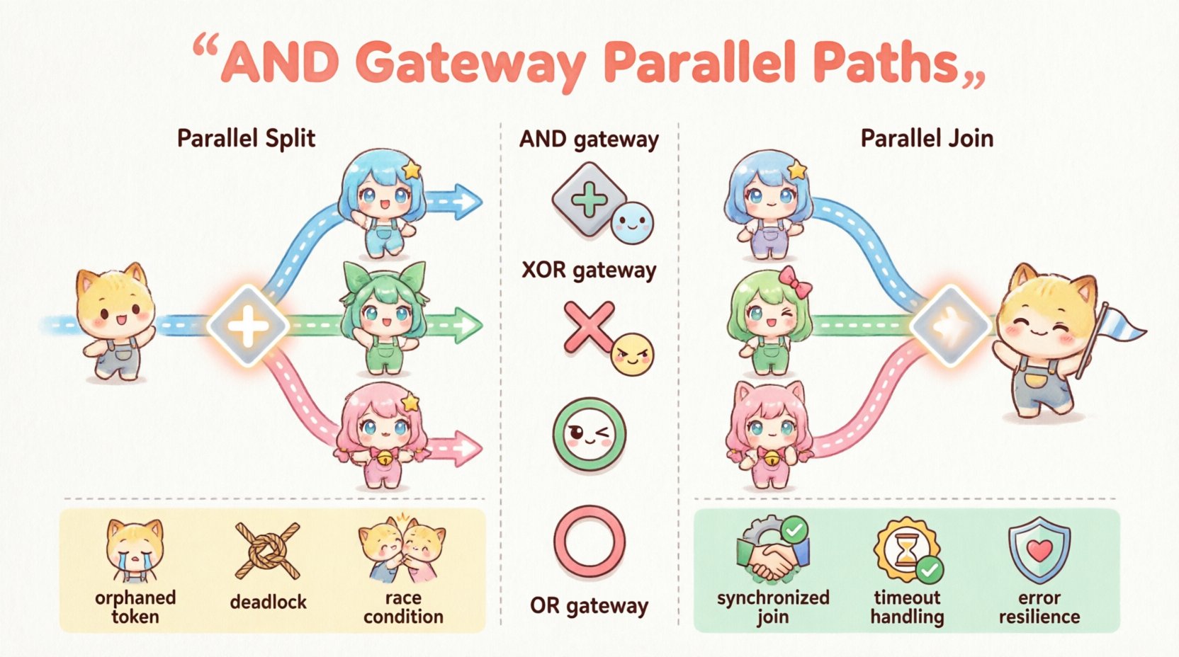
The AND Gateway is a decision point in a process diagram that controls the flow of tokens. Unlike an exclusive gateway (XOR), which chooses one path, the AND Gateway directs the flow to multiple paths simultaneously. It is visually represented by a diamond shape with a plus sign (+) inside.
There are two primary behaviors associated with this gateway:
- Parallel Split (Fork): Incoming flow triggers outgoing flows all at once.
- Parallel Join (Merge): Incoming flows must all arrive before proceeding.
When modeling, it is critical to distinguish between the gateway used for splitting the flow and the one used for joining it back together. While they share the same visual symbol, their functional roles differ based on the direction of the sequence flow.
Token Flow Logic: The Engine Behind the Model ⚙️
To model effectively, one must understand how the process engine handles tokens. A token represents the progress of a single process instance through the diagram. The behavior of the AND Gateway dictates how these tokens multiply and synchronize.
1. Parallel Split Behavior
When a token arrives at an AND Gateway configured as a split:
- The single incoming token is consumed.
- Multiple tokens are created, one for each outgoing sequence flow.
- All outgoing branches become active simultaneously.
This creates parallel execution threads. If Branch A takes 5 minutes and Branch B takes 2 minutes, the engine processes both independently. The token does not wait for Branch A to finish before starting Branch B.
2. Parallel Join Behavior
When tokens arrive at an AND Gateway configured as a join:
- The gateway waits until a token is present on all incoming sequence flows.
- Once the last token arrives, all incoming tokens are consumed.
- A single token is produced on the outgoing sequence flow.
This synchronization ensures that subsequent activities only begin once all parallel tasks are complete. This is vital for processes where a final approval depends on data gathered from multiple independent sources.
AND Gateway vs. Other Gateways 🔄
Selecting the correct gateway type is fundamental to process accuracy. Below is a comparison of gateway behaviors to clarify when to use an AND Gateway versus an XOR or OR Gateway.
| Gateway Type | Symbol | Split Logic | Join Logic | Use Case |
|---|---|---|---|---|
| AND Gateway | Plus (+) | All paths active | All paths required | Parallel tasks, synchronization |
| XOR Gateway | Cross (X) | One path active | One path arrives | Conditional routing, choices |
| OR Gateway | Circle (O) | One or more paths | One or more paths | Optional parallel tasks |
Step-by-Step Modeling Guide 🛠️
Follow these steps to implement parallel paths in your process diagram using standard modeling tools.
Step 1: Define the Trigger Event
Begin with a start event. This initiates the process and generates the initial token. Ensure the preceding logic (if any) leads cleanly into the gateway without ambiguity.
Step 2: Insert the Parallel Split Gateway
Drag an AND Gateway onto the canvas immediately after the start event or the preceding activity. Connect the incoming flow to the gateway.
Step 3: Create Outgoing Sequence Flows
Draw multiple outgoing arrows from the gateway. Each arrow represents a distinct parallel path. Label these flows clearly to indicate the specific task or sub-process they initiate.
Step 4: Model Independent Activities
On each branch, place the necessary tasks. These can be user tasks, service tasks, or sub-processes. Because they are parallel, the order of execution between branches is undefined. The engine may process them in any order.
Step 5: Insert the Parallel Join Gateway
Locate the point where all branches converge. Insert another AND Gateway. Ensure that every parallel branch has a sequence flow leading into this join gateway. Do not leave any incoming flow disconnected.
Step 6: Continue the Process
Connect a single outgoing sequence flow from the join gateway to the next phase of the process. This flow will only activate once all tokens from the parallel branches have arrived.
Handling Asynchronous Execution ⏳
In many real-world scenarios, parallel tasks are not truly synchronous. One branch might involve a database update, while another waits for an external email response. This introduces latency.
Managing Delays
The AND Gateway join logic inherently handles delays by waiting. However, this can lead to performance issues if one path is significantly slower than the others.
- Fast Path: Completes quickly and waits at the join.
- Slow Path: Takes longer. The join gateway holds the token until this path finishes.
To mitigate this, consider the business context. Is it acceptable for the process to wait? If the slow path is non-critical, you might use an OR Gateway instead to allow the process to continue without waiting for the delayed task.
Timeout Strategies
Some modeling environments allow for timer events attached to sequence flows. If a parallel branch exceeds a specific duration, a timer event can trigger an alternative path. This prevents the AND Gateway from waiting indefinitely.
Common Pitfalls and Error Handling ⚠️
Modeling parallel paths introduces complexity. Several common errors occur frequently when designers overlook specific requirements.
1. The Orphaned Token
This occurs when a parallel split creates a token, but the join gateway never receives it. This usually happens if:
- A branch is accidentally omitted in the join.
- A branch leads to an end event without returning to the main flow.
- A conditional flow bypasses the join gateway entirely.
Result: The process instance hangs or errors out because the engine is waiting for a token that will never arrive.
2. The Deadlock
A deadlock happens when tokens wait for each other in a circular dependency. While less common with simple AND gateways, it can occur in complex loops.
- Branch A waits for Branch B.
- Branch B waits for Branch A.
Result: The process stops completely. Review loop structures carefully to ensure exit conditions are met.
3. Race Conditions
If two parallel branches write to the same shared resource (e.g., a database record) without synchronization, data integrity may be compromised. The AND Gateway synchronizes the flow, but not necessarily resource access.
- Use intermediate events or transaction boundaries to manage shared data.
- Ensure service tasks are idempotent if retries occur.
Best Practices for Robust Modeling ✅
To maintain clarity and reliability in your process diagrams, adhere to these guidelines.
- Match Split and Join: Every split should have a corresponding join. If you fork, you must merge.
- Use Clear Labels: Label sequence flows to indicate why they are parallel (e.g., “Send Email”, “Update CRM”).
- Check Token Balance: Ensure the number of incoming flows at a join matches the number of outgoing flows at the split for simple flows.
- Avoid Nested Gateways: Keep gateway logic simple. Deep nesting makes debugging difficult.
- Validate Logic: Run a simulation if your tool supports it. Verify that all paths reach the end event.
Advanced Patterns: Nested AND Gateways 🔗
Complex processes often require multiple levels of parallelism. You can nest AND Gateways within sub-processes or main flows.
Scenario: Multi-Level Approval
Consider a scenario where a document requires approval from two departments simultaneously, and each department has two managers.
- Level 1 Split: Split into “Department A” and “Department B”.
- Level 2 Split (inside Dept A): Split into “Manager 1” and “Manager 2”.
- Level 2 Join (inside Dept A): Wait for both managers.
- Level 1 Join: Wait for both departments to return.
This structure ensures that the process only moves forward after all specific approvals are collected. It maintains the AND Gateway logic at every level of the hierarchy.
Exception Handling in Parallel Paths ❌
What happens if one branch fails? The behavior depends on how the process engine handles exceptions.
- Standard Behavior: If one branch fails, the token for that branch is consumed. The join gateway waits for the other branch. The process instance may end in an error state or continue depending on configuration.
- Error Sub-Processes: Use error boundary events on the tasks within the parallel branches. This allows the branch to handle the error locally without stopping the entire parallel flow.
- Compensation: If a parallel task completes but the data is invalid, compensation logic may be required to undo the work done by the other parallel branch.
Designers must decide whether the failure of one parallel task should abort the entire process or allow the other branch to finish. This decision often dictates the placement of error handlers.
Performance Implications 🚀
While parallel paths improve throughput, they increase resource consumption. The process engine must manage multiple threads or states for a single instance.
- Database Locking: More concurrent tokens may increase database contention.
- Memory Usage: Each active token requires memory to track state.
- Scalability: High-volume processes with many parallel splits require robust infrastructure.
When modeling, consider the volume of instances. A process that runs 10 times a day with parallel paths is different from one that runs 10,000 times a day. For high volume, ensure the parallel tasks are lightweight.
Summary of Implementation Considerations 📝
Modeling parallel paths using AND Gateways is a core competency for accurate business process representation. It enables organizations to reduce cycle times by executing tasks concurrently while maintaining data consistency through synchronization.
Key takeaways for effective implementation include:
- Use the AND Gateway for mandatory parallel execution.
- Ensure synchronization at the join point to prevent orphaned tokens.
- Account for latency differences between parallel branches.
- Implement error handling strategies specific to parallel logic.
- Validate the model to ensure all paths converge correctly.
By following these structural guidelines, you create a robust process model that aligns with operational realities. The AND Gateway remains one of the most powerful tools for optimizing workflow efficiency within the BPMN standard.