


Software development often stalls not because of code, but because of communication. Stakeholders describe what they need in natural language, while developers translate that into logic and structure. This translation gap frequently leads to misalignment. A robust method to bridge this gap is the Unified Modeling Language (UML). Specifically, the use case diagram serves as a critical tool for capturing functional requirements in a visual format.
This guide walks you through the process of transforming raw requirements into structured UML use cases. You will learn how to identify actors, define system boundaries, and map interactions without relying on specific tools. The focus remains on the conceptual workflow and the logic behind the modeling.
🧠 Understanding the Foundation: Requirements Engineering
Before drawing a single line, you must understand the input. Requirements are the specific conditions or capabilities that a system must satisfy. In the context of UML, we focus primarily on functional requirements—what the system does—though non-functional constraints influence the design.
Functional vs. Non-Functional Requirements
It is essential to distinguish between these two categories early in the process.
- Functional Requirements: These describe specific behaviors or functions. Examples include “The system shall allow users to reset passwords” or “The system shall calculate tax based on location.” These map directly to use cases.
- Non-Functional Requirements: These describe qualities of the system, such as performance, security, or reliability. Examples include “The system must respond within 2 seconds” or “Data must be encrypted.” While these do not become use cases directly, they constrain how use cases are implemented.
When gathering requirements, interview stakeholders and review documentation. Look for verbs and objects. Verbs often suggest actions (use cases), and objects suggest entities (actors or data).
🎭 Defining the Use Case Concept
A use case represents a specific goal that a user or external system achieves by interacting with the software. It is not a list of steps; it is a narrative of value. A single use case might encompass many steps, but it represents one cohesive objective.
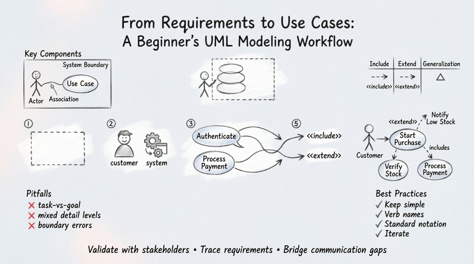
Key Components of a Use Case
To model this effectively, you need to understand the core elements:
- Actor: An entity that interacts with the system. Actors can be human users, other software systems, or hardware devices.
- System Boundary: The box that defines what is inside the system and what is outside. Anything interacting with the system but not inside the boundary is an actor.
- Use Case: The oval or rounded rectangle representing the functionality.
- Association: The line connecting an actor to a use case, indicating communication.
🚀 Step-by-Step Modeling Workflow
Creating a use case model is a systematic process. Follow these steps to ensure accuracy and completeness.
Step 1: Identify the System Boundary
Start by defining the scope. What is included in the system, and what is external? Draw a large box to represent this boundary. Everything that provides value to the actor must be inside this box. Anything outside is a resource or an actor.
Step 2: Identify the Actors
Scan your requirements for roles. Who is doing the work? Create a list of distinct roles.
- Primary Actors: Those who initiate the use case to achieve their own goal (e.g., a Customer placing an order).
- Secondary Actors: Those who provide services to the system (e.g., a Payment Gateway).
Tip: If two users perform the same actions and require the same permissions, group them into a single actor role called “User” or “Administrator.” This keeps the diagram clean.
Step 3: Define Use Cases
Look for verbs in your requirements. “Calculate,” “Register,” “Approve,” “Generate.” Each unique action often corresponds to a use case. Write the use case name as a verb phrase.
- Example: Instead of “Login,” use “Authenticate User.” Instead of “Report,” use “Generate Sales Report.”
Step 4: Map Relationships
Connect actors to use cases. If an actor interacts with a use case, draw a line. If multiple actors interact with the same use case, connect all of them. This visualizes who does what.
Step 5: Refine with Relationships
Not all interactions are simple associations. You may need to show how use cases relate to each other using specific relationships like Include and Extend.
| Relationship Type | Symbol | Meaning | Example |
|---|---|---|---|
| Include | Arrow with «include» | The base use case must use the included behavior. | “Place Order” includes “Validate Cart”. |
| Extend | Arrow with «extend» | The base use case may use the extending behavior under specific conditions. | “View Order” extends to “Show Error” if data is missing. |
| Generalization | Arrow with triangle | Inheritance of behavior between actors or use cases. | “Admin” is a generalization of “User”. |
📝 Detailed Example: E-Commerce Checkout
To illustrate this workflow, consider an online store requirement: “Users must be able to purchase items using a credit card. The system must verify stock before charging. If stock is low, the user must be notified. If stock is zero, the item cannot be purchased.” Here is how you translate that text into a model.
1. Extract Actors
- Customer: Initiates the purchase.
- Inventory System: External system that confirms stock levels.
2. Extract Use Cases
- Start Purchase: The main goal.
- Verify Stock: Required for every purchase.
- Process Payment: The core transaction.
- Notify Low Stock: Optional notification.
3. Define Relationships
- Start Purchase includes Verify Stock (Mandatory step).
- Start Purchase includes Process Payment (Mandatory step).
- Notify Low Stock extends Start Purchase (Conditional).
This structure ensures that the workflow logic is captured before any code is written.
⚠️ Common Pitfalls to Avoid
Beginners often struggle with the abstraction level. Here are frequent errors that reduce the value of your model.
1. Modeling Tasks Instead of Goals
A use case should represent a goal. “Click Button” is a task, not a use case. “Update Profile” is a goal. If you model tasks, your diagram becomes a user manual rather than a system specification.
2. Mixing Levels of Detail
Do not put high-level business goals and low-level technical steps in the same diagram. If “Search Product” is a use case, the internal steps of querying the database are not part of this diagram. Keep the scope consistent.
3. Ignoring the System Boundary
Ensure actors are outside the box. A common mistake is drawing an actor inside the system boundary. If the actor is part of the system logic, it is not an actor; it is a component.
4. Overusing Include and Extend
These relationships add complexity. Use them only when behavior is truly shared or conditional. Overusing them makes the diagram hard to read. Often, a simple association or a well-written use case description is sufficient.
🔗 Traceability: Connecting Requirements to Use Cases
Once your diagram is complete, you must ensure every requirement has a home. This is called traceability. It allows you to verify that nothing was missed during the analysis phase.
Create a mapping table to link your requirement IDs to your use case names.
| Requirement ID | Requirement Text | Mapped Use Case | Status |
|---|---|---|---|
| REQ-001 | System shall allow users to register. | Register User | Mapped |
| REQ-002 | System shall validate email format. | Register User (Included) | Mapped |
| REQ-003 | System shall send welcome email. | Send Welcome Email | Mapping Needed |
If a requirement has no mapped use case, you have a gap. If a use case has no mapped requirement, you might have scope creep. Review these gaps before proceeding to design.
🛠️ Validation Techniques
How do you know the model is correct? Use walkthroughs and validation techniques.
1. Walkthroughs with Stakeholders
Sit with the business owners and walk through the diagram. Ask them to describe a scenario. “How would I buy a shirt?” If they describe a process that isn’t in the diagram, add it. If they describe something that shouldn’t be there, remove it.
2. Consistency Checks
Ensure consistency across diagrams. If your Use Case Diagram shows “Admin” as an actor, your Class Diagram should reflect that role. If your Sequence Diagram shows a different flow, align them. UML is a language; all diagrams must speak the same syntax.
3. Completeness Check
Verify that all actors have at least one use case. An actor with no connections is usually a mistake. Verify that all use cases have at least one actor. A use case with no actor is a function with no user.
📈 Extending the Workflow: From Static to Dynamic
Use case diagrams are static. They show structure, not behavior over time. To fully define the workflow, you will eventually need sequence diagrams or activity diagrams. However, the use case diagram is the starting point.
For each use case in your diagram, you should eventually write a Use Case Specification. This document details the flow of events.
- Preconditions: What must be true before the use case starts? (e.g., User is logged in).
- Basic Flow: The happy path. The sequence of steps if everything goes right.
- Alternative Flows: What happens if things go wrong? (e.g., Password incorrect).
- Postconditions: What is true after the use case finishes? (e.g., Order is created).
This specification bridges the gap between the visual diagram and the actual code logic.
🎯 Best Practices for Beginners
To maintain clarity and authority in your models, adhere to these guidelines.
- Keep it Simple: A diagram with 50+ use cases is likely too large. Break it down. A system with many functions might need multiple diagrams (e.g., “Admin Panel” vs “Customer Portal”).
- Use Clear Naming: Use verbs. Avoid nouns. “Login” is better than “Login Screen.” “Calculate Tax” is better than “Tax Calculation.”
- Standardize Notation: Stick to standard UML symbols. Do not invent your own shapes. This ensures anyone familiar with UML can read your work.
- Iterate: Your first diagram will not be perfect. Expect to revise it as you learn more about the requirements. Models are living documents.
🤝 Collaboration and Feedback
Modeling is a social activity. Share your drafts early. Do not wait until the end to show your work. When stakeholders see their requirements visualized, they often realize misunderstandings immediately. This saves significant time and cost later in the development cycle.
Encourage questions. If a stakeholder looks confused by a relationship arrow, explain it. If they suggest a new actor, add it. The diagram belongs to the project team, not just the analyst.
📌 Summary of Key Takeaways
Transforming requirements into use cases requires discipline and attention to detail. By following a structured workflow, you ensure that the software built aligns with user needs.
- Identify Actors: Who interacts with the system?
- Define Goals: What does each actor want to achieve?
- Map Relationships: How do actors and use cases connect?
- Validate: Ensure all requirements are covered.
- Iterate: Refine the model as understanding grows.
Mastering this workflow does not happen overnight, but consistent practice builds competence. Focus on the logic and the value delivered, and the diagrams will naturally become clearer and more effective tools for communication.

