


In the architecture of software systems, clarity is paramount. A Class Diagram serves as the blueprint for understanding how data and behavior interact within an object-oriented design. These diagrams provide a static view of the system, detailing the structure of classes, their attributes, methods, and the relationships that bind them together. Whether you are designing a small utility or a large-scale enterprise application, mastering this visual language ensures that the logic holds up under scrutiny.
This guide breaks down the mechanics of UML class diagrams. We will explore the core components, the various ways classes interact, and the principles that lead to maintainable code. By the end, you will have a solid grasp of how to translate abstract requirements into concrete structural models.
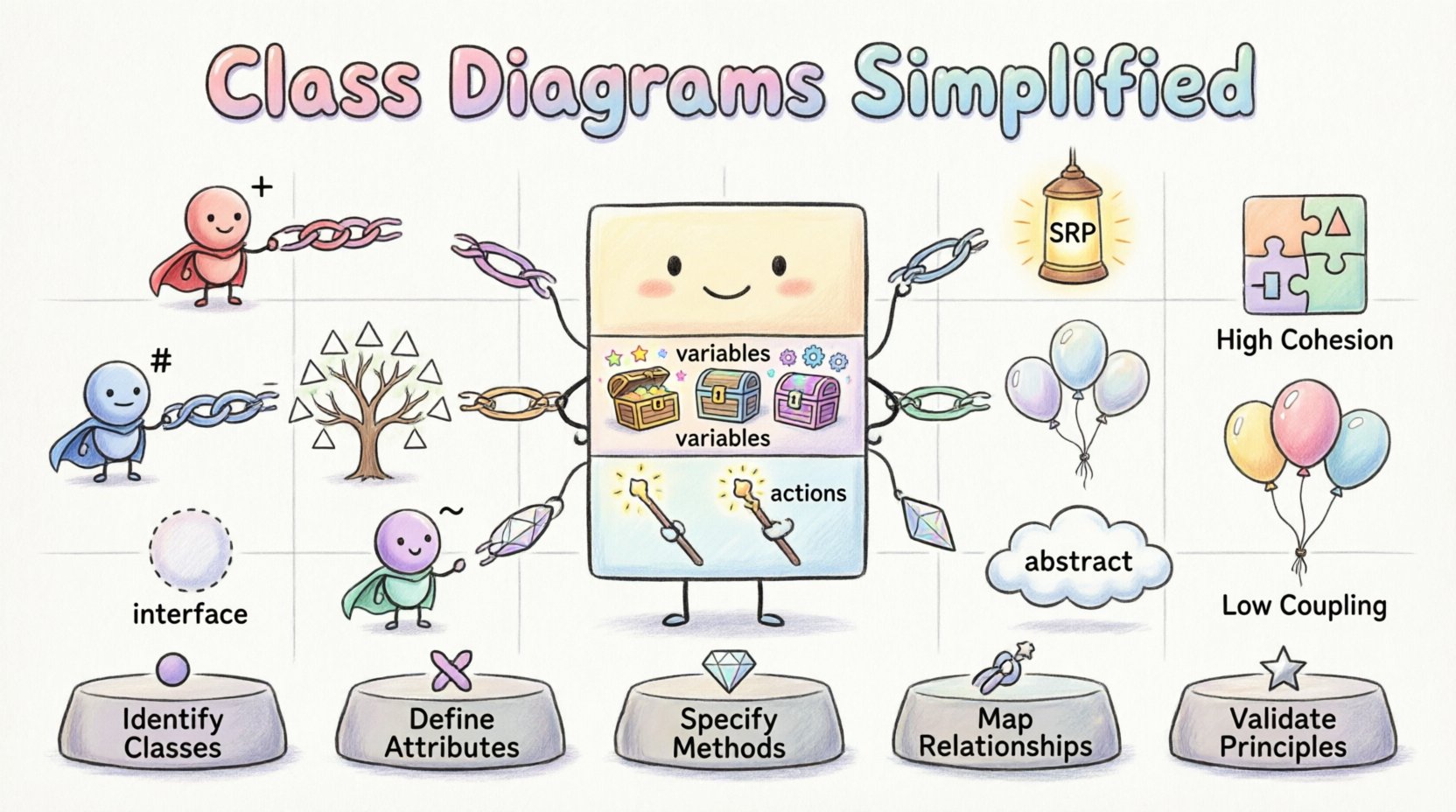
🏗️ The Anatomy of a Class
At the heart of every class diagram is the class itself. In Unified Modeling Language (UML), a class is represented by a rectangle divided into three distinct compartments. This structure is not arbitrary; it maps directly to how programming languages organize data and logic.
1. The Class Name Compartment
The top section contains the identifier for the class. This name should be a noun, reflecting the entity being modeled. For example, Customer, Order, or PaymentGateway.
- Capitalization: Use PascalCase (e.g., InvoiceRecord) for class names.
- Abstract Classes: If a class cannot be instantiated directly, it is often represented with italics.
- Static Classes: Some frameworks denote classes that hold only static members with specific notation, though standard UML relies on the compartment below.
2. The Attributes Compartment
Below the name lies the list of attributes. These represent the state or data stored within an instance of the class. Think of attributes as the variables that define what the object knows about itself.
- Data Types: Specify the type of data (e.g., String, Integer, Boolean).
- Visibility: Precede the attribute name with a symbol indicating access level (see table below).
- Initial Values: You may assign a default value (e.g., status = "active").
3. The Methods Compartment
The bottom section lists the operations or methods. These define the behavior of the class—what the object can do. Methods manipulate attributes or interact with other classes.
- Parameters: List input arguments within parentheses (e.g., calculateTax(amount)).
- Return Types: Indicate the output data type if applicable.
- Visibility: Same symbols as attributes apply here.
Visibility Modifiers
Understanding access control is vital for encapsulation. The following table outlines standard UML visibility symbols:
| Symbol | Modifier | Description |
|---|---|---|
| + | Public | Accessible from any other class. |
| – | Private | Accessible only within the class itself. |
| # | Protected | Accessible within the class and its subclasses. |
| ~ | Package/Default | Accessible within the same package or namespace. |
🔗 Defining Relationships
Classes rarely exist in isolation. They communicate and rely on one another. Relationships define these connections. In UML, these are depicted using lines connecting the class rectangles, often with arrows or specific symbols to denote direction and cardinality.
Association
An association represents a structural relationship where objects are linked. It implies that one class knows about another and can navigate to it.
- Direction: A line with an arrowhead indicates navigability (who knows about whom).
- Multiplicity: Numbers or ranges (e.g., 1, 0..1, *) define how many instances participate.
- Example: A Professor teaches Students. One Professor can teach many Students.
Dependency
A dependency is a weaker relationship. It signifies that a change in one class may affect another, but they do not necessarily hold references to each other. It is often a temporary relationship.
- Notation: A dashed line with an open arrowhead.
- Usage: Often seen when a method parameter or local variable uses a class type.
- Example: A ReportGenerator class uses a DatabaseConnector to fetch data but does not store it.
Inheritance (Generalization)
Inheritance allows a new class to inherit attributes and methods from an existing class. This promotes code reuse and establishes an “is-a” relationship.
- Notation: A solid line with a hollow triangle arrowhead pointing to the superclass.
- Subclass: The class at the arrow tail is the subclass.
- Superclass: The class at the arrow head is the superclass.
- Example: A SavingsAccount is a BankAccount.
Aggregation
Aggregation represents a “whole-part” relationship where the part can exist independently of the whole. It is a specialized form of association.
- Notation: A solid line with a hollow diamond at the “whole” end.
- Lifecycle: The part can survive the destruction of the whole.
- Example: A Department contains Employees. If the Department is dissolved, the Employees still exist.
Composition
Composition is a stronger form of aggregation. The part cannot exist without the whole. This is a “has-a” relationship with a strict lifecycle dependency.
- Notation: A solid line with a filled diamond at the “whole” end.
- Lifecycle: When the whole is destroyed, the parts are destroyed.
- Example: A House is composed of Rooms. If the House is demolished, the Rooms cease to exist in that context.
⚙️ Advanced Modeling Concepts
Beyond the basics, complex systems require more nuanced modeling. These concepts help manage complexity and enforce architectural constraints.
Interfaces
An interface defines a contract of behavior without implementing it. It specifies a set of methods that a class must implement.
- Notation: A class name prefixed with <<interface>> or a circle connected by a dotted line.
- Usage: Useful for decoupling components. Classes implement interfaces rather than inheriting from abstract classes.
- Benefit: Allows different implementations to swap seamlessly.
Abstract Classes
Abstract classes cannot be instantiated directly. They serve as a base for other classes, providing common implementation while leaving specific details to subclasses.
- Notation: Class name is often italicized.
- Usage: When there is a clear hierarchy but some behavior varies significantly.
- Benefit: Enforces a structure without dictating every detail.
Static Members
Static attributes and methods belong to the class itself rather than instances of the class. There is only one copy shared by all instances.
- Notation: Underlined text in the compartment.
- Usage: Configuration settings, utility functions, or singletons.
🛠️ Design Principles for Class Diagrams
A well-constructed diagram is not just a drawing; it reflects sound engineering practices. Adhering to specific principles ensures the resulting code is robust and adaptable.
Single Responsibility Principle (SRP)
Each class should have one reason to change. If a class handles database connections, formatting, and user authentication, it is too complex.
- Splitting: Break large classes into smaller, focused classes.
- Benefit: Easier to test and maintain.
High Cohesion, Low Coupling
Cohesion refers to how closely related the responsibilities of a single class are. Coupling refers to how dependent one class is on another.
- High Cohesion: Methods in a class work together to fulfill a single goal.
- Low Coupling: Changes in one class do not ripple through the system.
- Strategy: Use interfaces to reduce direct dependencies.
Encapsulation
Hide the internal state of an object. Expose only what is necessary through public methods.
- Visibility: Keep attributes private.
- Accessors: Use getters and setters to control data access.
🔄 Common Pitfalls and Solutions
Even experienced architects encounter challenges when modeling systems. Recognizing these common issues can save significant time during development.
Pitfall 1: Over-Engineering
Creating a diagram with too many levels of abstraction can confuse stakeholders. Start simple.
- Solution: Model the core domain first. Add interfaces and advanced patterns only when complexity demands it.
Pitfall 2: Circular Dependencies
Class A depends on Class B, which depends on Class A. This creates a loop that is difficult to resolve in code.
- Solution: Introduce an interface or a third class to break the cycle.
Pitfall 3: Ignoring Multiplicity
Forgetting to specify how many objects are involved in a relationship leads to ambiguous requirements.
- Solution: Always define cardinality (e.g., 1 to Many, 0 to Many).
Pitfall 4: Mixing Concepts
Using inheritance for behavior sharing instead of composition. Inheritance is for “is-a” relationships; composition is for “has-a” relationships.
- Solution: Prefer composition over inheritance for flexibility.
📝 Best Practices for Documentation
A class diagram is a living document. It should evolve with the system. Here are guidelines for maintaining clarity.
- Consistency: Use the same naming conventions throughout all diagrams.
- Annotations: Add notes to explain complex logic that cannot be shown in the box.
- Versioning: Track changes to the diagram as the codebase evolves.
- Readability: Arrange classes logically. Group related classes together to minimize crossing lines.
🚀 Workflow for Creating Diagrams
While tools vary, the process of modeling remains consistent. Follow these steps to build a reliable structure.
- Identify Entities: Review requirements to find the key nouns (objects).
- Define Attributes: Determine what data each entity needs to store.
- Define Methods: Determine what actions each entity can perform.
- Map Relationships: Draw lines to show how entities connect and interact.
- Refine: Review the diagram for violations of design principles (e.g., high coupling).
- Validate: Walk through a scenario using the diagram to ensure logic holds.
💡 Real-World Application Example
Consider an E-Commerce system. Here is how a simplified model might look.
- Product: Attributes include id, price, stock. Methods include updatePrice().
- Cart: Contains a collection of Product objects (Aggregation). Methods include addItem().
- Order: Created from a Cart (Composition). Contains OrderItems.
- Payment: An interface implemented by CreditCard and PayPal.
This structure ensures that the shopping cart can exist without an order, but an order cannot exist without payment details. It separates the logic of selling from the logic of paying.
🔍 Reviewing and Refactoring
Once the initial diagram is complete, it requires review. Look for:
- Redundancy: Are attributes repeated across classes that could be shared?
- Missing Links: Are there data flows that have no corresponding class?
- Complexity: Are there classes with too many methods? Split them.
- Clarity: Is the diagram readable for new team members?
Refactoring the diagram is as important as refactoring the code. A diagram that no longer matches the system is worse than no diagram at all, as it creates false expectations.
📈 Conclusion
Class diagrams are the foundation of object-oriented communication. They translate abstract business needs into a technical structure that developers can implement. By understanding attributes, methods, and relationships, you gain the ability to design systems that are flexible, scalable, and easy to maintain.
Remember that the goal is not perfection on the first try. It is clarity. Use these tools to facilitate discussion, identify gaps in logic, and guide the implementation process. With practice, modeling becomes a natural part of the development workflow.

