


Unified Modeling Language serves as a standard notation for specifying, constructing, and documenting the artifacts of software systems. Within this framework, the Class Diagram stands as the primary structural model. It describes the static structure of a system by showing its classes, attributes, operations, and the relationships among objects. Understanding how to connect these classes effectively is crucial for creating clear and maintainable designs. This guide explores the core relationships used to link classes together, ensuring your models communicate intent accurately without ambiguity.
Effective modeling requires more than just drawing boxes and lines. It demands a deep understanding of the semantic meaning behind every connection. When you define a relationship, you are defining how data flows, how responsibilities are shared, and how objects interact within the system’s lifecycle. This comprehensive resource covers Association, Inheritance, Dependency, and more, providing the technical depth needed to create robust diagrams.
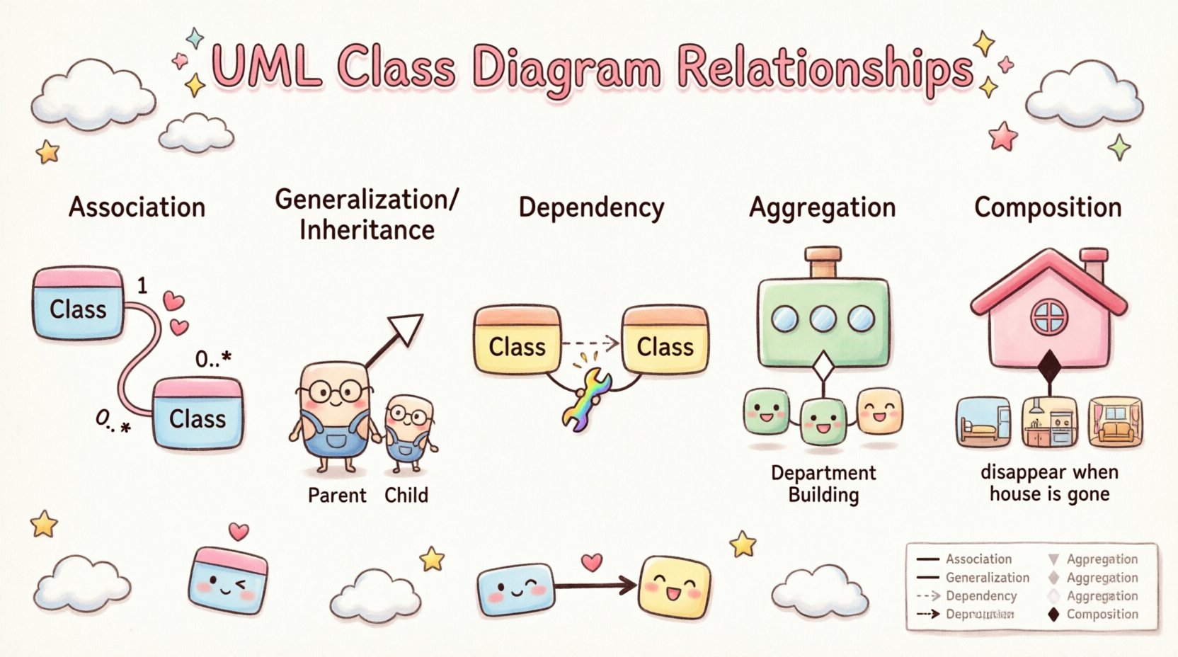
🔗 Understanding Association Relationships
An association represents a structural relationship between two or more classes. It indicates that objects of one class are connected to objects of another class. In practical terms, this means that an instance of one class holds a reference to an instance of another class. This is the most fundamental relationship type in object-oriented design.
Associations can be unidirectional or bidirectional. The direction of the association determines which class is aware of the other. If Class A knows about Class B, but Class B does not know about Class A, the association is unidirectional. If both classes maintain references to each other, it is bidirectional.
📊 Multiplicity and Cardinality
Multiplicity is a critical aspect of association modeling. It defines how many instances of one class relate to one instance of another. This constraint helps clarify the business rules embedded in the system design. Common multiplicity notations include:
- 1: Exactly one instance.
- 0..1: Zero or one instance (optional).
- 1..*: One or more instances (mandatory).
- 0..*: Zero or more instances (optional).
- *: Same as 0..*, representing many.
For example, consider a library system. A Member can borrow many Books, but a Book is typically associated with one Member at a specific time. This creates a one-to-many relationship. The notation would place a 1 near the Book class and a 0..* near the Member class.
🧭 Navigability and Roles
Navigability indicates the direction in which the relationship can be traversed. If a line has an arrowhead pointing from Class A to Class B, it means objects of Class A can navigate to objects of Class B. This is often implied by the direction of the association line.
Roles are names assigned to the ends of an association. They describe the function of the object at that end of the relationship. For instance, in a relationship between Doctor and Patient, the role at the Doctor end might be labeled treating, and the role at the Patient end might be labeled receiving care.
📉 Inheritance and Generalization
Inheritance, often referred to as Generalization in UML, represents an is-a relationship. It allows a class to inherit attributes and operations from another class. The class that inherits is called the subclass or derived class. The class being inherited from is the superclass or base class.
✅ Benefits of Inheritance
- Code Reuse: Common attributes and operations are defined once in the superclass, reducing redundancy.
- Polymorphism: Subclasses can be treated as instances of the superclass, allowing for flexible method calls.
- Extensibility: New behaviors can be added to subclasses without modifying the existing superclass.
📐 Visual Notation
The visual representation of inheritance is a solid line with a hollow triangle arrowhead pointing toward the superclass. This arrow indicates the direction of the inheritance hierarchy.
For example, consider a shape hierarchy. You might have a Shape superclass with attributes like color and fillStyle. Subclasses such as Circle, Rectangle, and Triangle would inherit from Shape. Each subclass might add specific attributes, like radius for Circle or width and height for Rectangle.
⚠️ Design Considerations
While inheritance is powerful, it should be used judiciously. Deep hierarchies can become difficult to maintain. It is often better to limit inheritance to two or three levels. If a relationship feels like a has-a relationship rather than an is-a relationship, composition or aggregation might be more appropriate.
🔌 Dependency Relationships
A dependency relationship represents a use-a relationship. It indicates that a change in the specification of one thing may affect the other things that depend on it. This is a weaker form of association where the connection is typically temporary.
📝 Scenarios for Dependency
Dependencies often occur in the following scenarios:
- Parameters: A method in one class accepts an object of another class as a parameter.
- Local Variables: A method creates a local variable of another class to perform a task.
- Static Methods: A method in one class calls a static method of another class.
- Return Types: A method returns an object of another class.
📐 Visual Notation
The dependency relationship is depicted using a dashed line with an open arrowhead pointing from the dependent class (the client) to the supplier class (the supplier). This visual distinction helps modelers quickly identify temporary couplings versus permanent structural links.
For instance, a ReportGenerator class might depend on a DataFetcher class. The ReportGenerator does not own the DataFetcher; it simply uses it to retrieve information. If the DataFetcher changes its interface, the ReportGenerator might break, but the DataFetcher does not need to know about the ReportGenerator.
💎 Aggregation vs. Composition
Both Aggregation and Composition are special forms of association that describe a part-of relationship. The distinction lies in the lifecycle management and ownership strength.
🔹 Aggregation (Weak Ownership)
Aggregation implies that the part can exist independently of the whole. The lifecycle of the part is not strictly controlled by the whole.
- Example: A Department has Employees. If the Department is dissolved, the Employees still exist and can move to other departments.
- Notation: A solid line with a hollow diamond at the end of the whole class.
🔸 Composition (Strong Ownership)
Composition implies that the part cannot exist independently of the whole. The lifecycle of the part is controlled by the whole. If the whole is destroyed, the parts are destroyed as well.
- Example: A House has Rooms. If the House is demolished, the Rooms cease to exist.
- Notation: A solid line with a filled diamond at the end of the whole class.
📋 Relationship Comparison Table
| Relationship Type | Visual Notation | Meaning | Lifecycle |
|---|---|---|---|
| Association | Solid Line | Structural link | Independent |
| Generalization | Line with Hollow Triangle | Is-a relationship | Inherited |
| Dependency | Dashed Line with Open Arrow | Use-a relationship | Temporary |
| Aggregation | Line with Hollow Diamond | Has-a relationship (Weak) | Independent |
| Composition | Line with Filled Diamond | Has-a relationship (Strong) | Dependent |
🛠️ Best Practices for Modeling
Creating effective class diagrams requires adherence to established conventions. Following these practices ensures that your models remain understandable as the system grows.
📌 Naming Conventions
Use clear and descriptive names for classes and relationships. Class names should be nouns (e.g., Customer, Order). Association names should be verbs (e.g., places, owns). Role names should describe the context of the relationship.
📌 Avoiding Cycles
Circular dependencies can lead to complex initialization issues and tight coupling. While some cycles are unavoidable in complex systems, try to minimize them. If Class A depends on Class B, and Class B depends on Class A, consider extracting common functionality into a third class.
📌 Visibility Modifiers
Define the visibility of attributes and operations using standard symbols:
- +: Public
- –: Private
- #: Protected
- ~: Package (default)
Visibility controls access to members. Private members are only accessible within the class itself, while public members are accessible to any other class. This encapsulation is vital for maintaining data integrity.
📌 Constraints and Notes
Use constraints to add specific rules to your diagram. These are often enclosed in curly braces {constraint}. For example, you might specify {readOnly} on an attribute or {pre: amount > 0} on an operation.
Notes can be added to provide additional context or explanations that do not fit into the standard class structure. These appear as a rectangle with a folded corner.
🧩 Common Mistakes to Avoid
Even experienced modelers can fall into traps when designing class diagrams. Being aware of these common pitfalls helps in creating cleaner models.
- Over-engineering: Creating too many levels of inheritance or unnecessary relationships can make the system harder to understand. Start simple and refactor later.
- Confusing Dependency and Association: A dependency is temporary, while an association is structural. If a class holds a reference to another class as a member variable, it is usually an association, not a dependency.
- Ignoring Multiplicity: Failing to specify multiplicity leaves the model ambiguous. Always define how many objects can be involved in a relationship.
- Missing Navigation: If a relationship is unidirectional, ensure the arrow points in the correct direction. This affects how code is generated and how objects are accessed.
🌐 Real-World Application Scenarios
To illustrate these concepts, consider an e-commerce platform architecture.
Order Processing
In this scenario, a Customer places an Order. This is an Association. One Customer can place many Orders (1..*). The Order contains OrderItems.
An OrderItem depends on a Product. The OrderItem does not own the Product; it just references it for pricing and description. This is a Dependency.
A Product is composed of Categories. If the Category is deleted, the Product relationship changes significantly. This suggests Composition.
User Authentication
A User class might inherit from a Person class. This is Generalization. The User class adds attributes like username and passwordHash.
A SessionManager depends on the User class to validate credentials. This is a Dependency.
🔍 Refining Your Model
Once the initial relationships are drawn, review the diagram for consistency. Check if all necessary attributes and operations are present. Ensure that the relationships align with the business logic. Iterative refinement is key to a successful design.
Consider the flow of data. Does every class have a clear path to the data it needs? Are there classes that are too large or too small? Adjusting the granularity of your classes can improve the overall quality of the design.
📝 Final Thoughts on Modeling
Modeling relationships in UML Class Diagrams is a skill that combines technical precision with creative problem-solving. By understanding the nuances of Association, Inheritance, Dependency, Aggregation, and Composition, you can create diagrams that serve as effective blueprints for software development.
Focus on clarity and communication. Your diagrams should be understandable by developers, stakeholders, and future maintainers. Use the visual tools available to distinguish between different types of connections. Remember that a diagram is a living document; it should evolve as the system evolves.
Adhering to these principles will result in robust architectures that are easier to implement, test, and maintain. Take the time to get the relationships right, as they form the backbone of your object-oriented design.

