


The divide between design and implementation is a persistent challenge in software engineering. Architects often produce detailed Unified Modeling Language (UML) specifications that sit in repositories, while developers write code that diverges from the original vision. This guide provides a pragmatic approach to bridging that gap. We explore how to translate abstract diagrams into tangible, maintainable software artifacts without relying on specific tooling ecosystems.
The goal is not just to draw pictures, but to establish a reliable pipeline where design intent flows directly into executable logic. This involves understanding the semantics of modeling notations, applying strict mapping rules, and maintaining synchronization throughout the lifecycle. By treating models as executable specifications rather than static documentation, teams can reduce errors and improve consistency.
🔌 Why the Gap Exists: Design vs. Implementation
Many projects fail to realize the full potential of modeling because the tools used for design do not integrate with the environment used for coding. When a diagram is created in one system and code is written in another, manual transcription errors become inevitable. The model becomes outdated before the first commit is made.
To address this, the workflow must support bidirectional communication. This means:
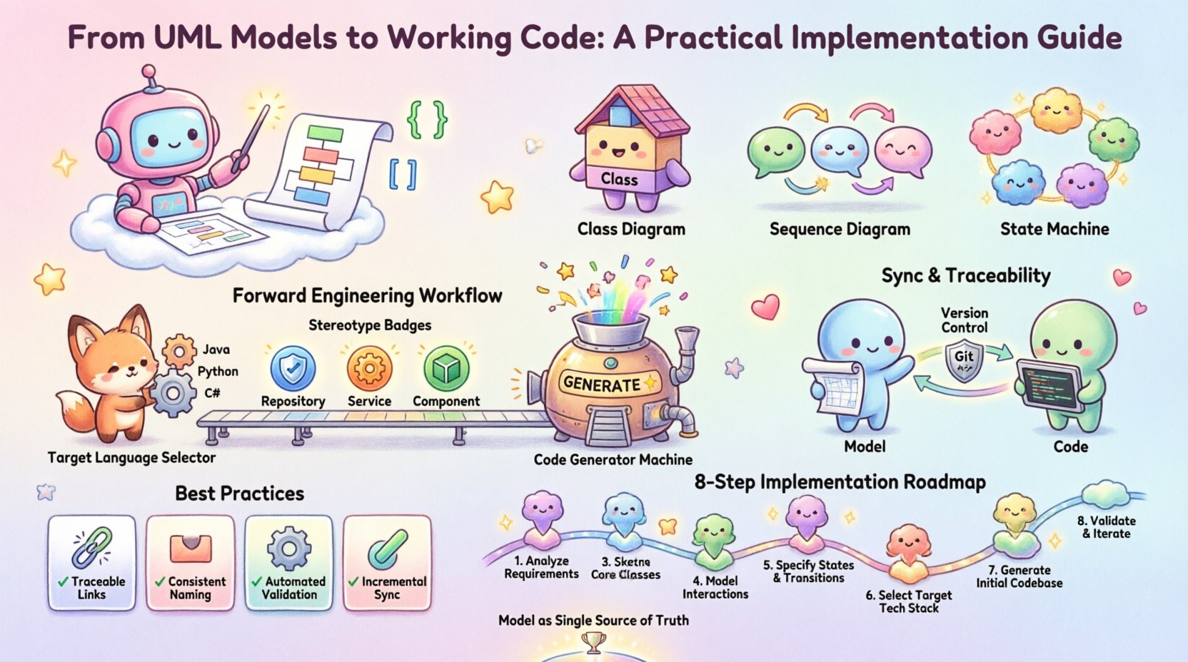
- Consistency: The code must reflect the structure defined in the model.
- Traceability: Every line of code should be traceable back to a design element.
- Automation: Repetitive tasks like boilerplate generation should be handled by the platform.
When these conditions are met, the model acts as a single source of truth. This reduces the cognitive load on developers who no longer need to remember every interface contract or data structure detail. It also ensures that architectural decisions are enforced at the compilation level.
📐 Essential Diagrams for Implementation
Not all diagrams serve the purpose of implementation. Some are for stakeholder communication, while others drive the build process. For generating working code, specific diagram types carry the most weight.
Class Diagrams: The Backbone
The class diagram is the primary source for structural code generation. It defines the skeleton of the application. When translating these to code, attention must be paid to:
- Visibility Modifiers: Private, protected, and public attributes map directly to access control keywords.
- Abstract Classes: These indicate base classes that should not be instantiated directly.
- Interfaces: These define contracts that multiple classes must implement.
- Relationships: Inheritance, association, and dependency must be mapped to language-specific features like extends, implements, or references.
Sequence Diagrams: Behavior Logic
While class diagrams define structure, sequence diagrams define behavior. They show how objects interact over time. For implementation, these are crucial for:
- Method Signatures: The flow of messages determines the parameters and return types of methods.
- Control Flow: Loops, conditionals, and exception handling become apparent in the message exchanges.
- State Transitions: Complex state changes can be visualized to prevent logic errors.
State Machine Diagrams: State Management
For systems with complex lifecycles (e.g., order processing, user authentication), state machine diagrams are essential. They prevent code from becoming a “spaghetti” of if-else statements. Instead, they encourage:
- Event-Driven Architecture: Code reacts to specific triggers.
- State Encapsulation: Logic is grouped by the state of the object.
- Transition Guards: Conditions for moving between states are explicit.
🛠️ The Forward Engineering Workflow
Forward engineering is the process of generating code from the model. This is often the first step in a Model-Driven approach. The process requires a clear definition of the target environment.
Step 1: Define the Target Language
The model must be agnostic enough to support multiple targets, or specific profiles must be created for each language. A model designed for a Java environment will differ significantly from one designed for C# or Python. Key considerations include:
- Typing Systems: Strongly typed languages require explicit type declarations in the model.
- Memory Management: Garbage collection vs. manual memory management affects lifecycle constraints.
- Concurrency Models: Threading, async/await, or event loops must be reflected in the design.
Step 2: Map Stereotypes to Constructs
Standard UML elements cover most needs, but specialized stereotypes add value. For example:
- <<Repository>>: Maps to database persistence layers or ORM entities.
- <<Service>>: Maps to business logic layers or API endpoints.
- <<Component>>: Maps to deployable units or microservices.
Step 3: Generate Artifacts
The generation engine processes the model and produces source files. This is not merely text substitution; it involves structural analysis. The generator must:
- Create package structures based on namespace definitions.
- Establish file dependencies based on import statements.
- Insert comments that link code back to the diagram node.
🔄 Keeping Models and Code in Sync
The biggest risk in model-driven development is divergence. If developers modify code without updating the model, the model becomes a lie. If architects update the model without regenerating code, the system is broken. A synchronization strategy is mandatory.
Round-Trip Engineering
This technique allows changes in the code to be reflected in the model and vice versa. It requires the modeling tool to parse the source code and compare it against the model definition.
- Code to Model: Detects new methods, removed classes, or changed signatures.
- Model to Code: Applies design changes to the implementation.
Handling Conflicts
When both the model and code change independently, conflicts arise. A robust workflow includes:
- Version Control: Both model files and source code must be tracked in the same repository.
- Build Scripts: Automated processes run checks to ensure the latest model generates the current codebase.
- Manual Intervention: Complex logic changes should be flagged for human review before regeneration.
🧩 Common Implementation Challenges
Even with a solid strategy, practical issues arise. Understanding these pitfalls helps teams avoid costly rework.
Over-Modeling
Creating diagrams for every minor detail leads to maintenance overhead. If a diagram takes longer to update than the code it represents, it is a liability. Focus on:
- Core architectural components.
- Complex logic flows.
- Public interfaces and APIs.
Stale Documentation
Teams often abandon the model after the initial phase. To prevent this, the model must be part of the Definition of Done. A feature is not complete until the model is updated.
Loss of Nuance
UML is visual, but code is textual. Some language-specific nuances (e.g., operator overloading, macros, decorators) may not have direct UML equivalents. The model should focus on the logic, while the code handles the syntax.
📋 Strategic Best Practices
The following table summarizes key decisions and their impact on the implementation process.
| Decision Point | Recommendation | Impact on Code |
|---|---|---|
| Diagram Granularity | High-level architecture + detailed class diagrams | Reduces boilerplate generation noise |
| Update Frequency | Continuous integration | Ensures model accuracy at all times |
| Manual vs. Auto | Hybrid approach | Allows custom logic in generated code |
| Version Control | Unified repository | Prevents drift between artifacts |
🧪 Testing the Generated Output
Generating code is only half the battle. The output must be verified. Automated testing frameworks should be integrated into the pipeline.
- Unit Tests: Verify that generated methods behave as expected based on sequence diagrams.
- Integration Tests: Ensure generated components interact correctly.
- Static Analysis: Run linters to ensure generated code follows style guides.
🔄 Refactoring and Evolution
Software evolves. Requirements change. The model must evolve with it. When refactoring, it is often better to update the model first, then regenerate. This ensures the design intent is preserved.
Pattern Application
Common design patterns can be modeled explicitly to guide generation.
- Singleton: Modeled as a class with a private constructor and static instance.
- Factory: Modeled as a separate class responsible for instantiation.
- Observer: Modeled using interface inheritance and listener methods.
🌐 Future Considerations
The landscape of model-driven development is shifting. With the rise of AI-assisted coding, the distinction between design and implementation is blurring. Generative models can now suggest UML structures based on code and vice versa.
- AI Integration: Tools that suggest diagram improvements based on code quality.
- Low-Code Platforms: Visual builders that output production-ready code directly.
- Standardization: Industry standards are evolving to support richer metadata in models.
The core principle remains the same: clarity of intent. Whether generated by AI or manually crafted, the model must serve as a reliable blueprint. Developers should focus on the logic and structure, knowing the implementation details are handled by the system. This separation of concerns allows for higher quality software and faster delivery cycles.
🛠️ Summary of Implementation Steps
To successfully move from UML to code, teams should follow this structured path:
- Analyze Requirements: Identify what needs to be modeled.
- Create Initial Models: Draft class and sequence diagrams.
- Configure Generator: Set up the environment for code output.
- Generate Initial Code: Produce the first version of the source.
- Implement Business Logic: Fill in the gaps left by the generator.
- Synchronize: Ensure changes are reflected in both model and code.
- Test: Validate the generated artifacts.
- Iterate: Update models as requirements evolve.
By adhering to these practices, organizations can leverage UML not as a documentation burden, but as a powerful engine for software creation. The model becomes the contract that ensures the final product matches the architectural vision, reducing technical debt and improving long-term maintainability.

