


Understanding the structural integrity of a software system requires more than just knowing what components exist. It demands a clear comprehension of how those components interact within a physical or virtual infrastructure. In the context of system architecture, the deployment diagram serves as the blueprint for this interaction. At the heart of this diagram lie two fundamental concepts: nodes and artifacts. Grasping the relationship between them is essential for designing robust, scalable, and maintainable systems. This guide explores the intricacies of these relationships, providing a technical overview for architects and engineers.
Understanding Execution Environments: The Node 🖥️
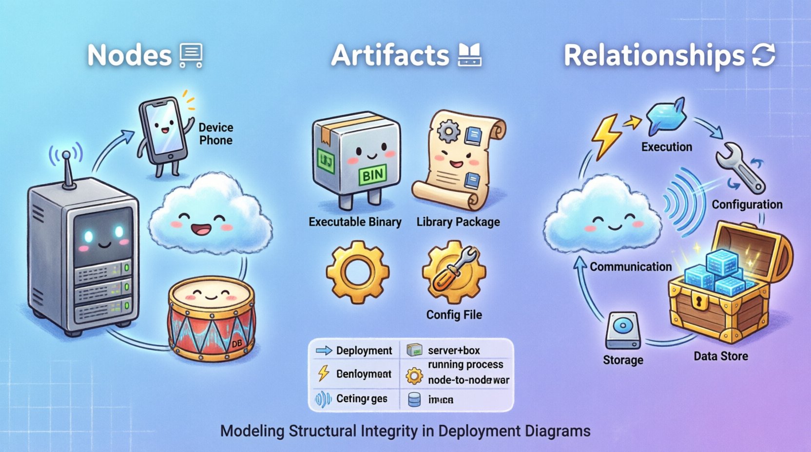
A node represents a computational resource where software components execute. It is not merely a server; it is the environment that provides the runtime capabilities necessary for an artifact to function. In modeling, nodes define the boundaries of deployment and resource allocation.
Types of Nodes
Nodes can be categorized based on their physical nature and logical role:
- Physical Nodes: These represent tangible hardware. They include dedicated servers, mainframes, or embedded devices. Physical nodes have specific constraints regarding memory, processing power, and connectivity.
- Logical Nodes: These represent abstract environments that host multiple components. Examples include application containers, virtual machines, or process groups. Logical nodes allow for better abstraction when the underlying hardware topology is complex or hidden.
- Device Nodes: These represent end-user hardware or network devices. They include workstations, mobile devices, routers, and switches. Device nodes often have limited processing capabilities compared to server nodes.
- Software Nodes: In some modeling standards, a node can represent a specific software environment, such as a database engine or a web server instance. This blurs the line between the hardware and the software layer.
Node Characteristics
When defining a node, specific attributes must be considered to ensure accurate modeling:
- Connectivity: How the node connects to other nodes. Is it via a LAN, WAN, or the public internet? Protocols such as TCP/IP or HTTP define this connection.
- Storage Capacity: The available disk space for storing artifacts and data.
- Processing Power: The CPU capacity available for executing tasks.
- Operating System: The underlying software environment that dictates which artifacts can be deployed.
Understanding Physical Components: The Artifact 📦
An artifact is a physical representation of a software unit. It is the file or collection of files that gets deployed to a node. Unlike a class or component in a design model, an artifact exists on the file system. It is the tangible deliverable of the development process.
Types of Artifacts
Artifacts vary significantly based on their function and format:
- Executable Artifacts: These are binary files or scripts that run directly. Examples include compiled binaries, shell scripts, or container images.
- Library Artifacts: These provide shared functionality to executables. They include dynamic link libraries, shared objects, or dependency packages.
- Configuration Artifacts: These define how the system behaves. Examples include property files, environment variables, or XML configuration documents.
- Data Artifacts: These represent persistent data stores. Examples include database schema files, seed data, or binary blobs.
- Documentation Artifacts: While not executed, these are deployed for operational reference. Examples include API specifications or user manuals.
Artifact Lifecycle
Artifacts move through a lifecycle from creation to retirement:
- Creation: Built by a compilation or build process.
- Storage: Stored in a repository or artifact registry.
- Deployment: Copied or moved to the target node.
- Execution: Loaded and run by the node environment.
- Management: Updated, patched, or retired over time.
The Relationship Between Node and Artifact 🔄
The core of a deployment diagram is the association between a node and an artifact. This relationship defines where code lives and how it runs. Without a clear definition of this link, the architecture becomes ambiguous, leading to deployment errors and configuration drift.
Deployment Association
A deployment association indicates that an artifact is installed or executed on a specific node. It implies a physical or logical mapping. For example, a web application artifact is deployed to a web server node. This relationship is often directional, showing the flow from the repository to the execution environment.
Dependency Relationships
Artifacts often depend on other artifacts or node capabilities. A node might provide the runtime environment (e.g., a specific version of a language interpreter) required by an artifact. If the node does not support the artifact’s requirements, deployment fails.
Communication Relationships
While nodes communicate with other nodes, artifacts within those nodes communicate via the node’s network interface. Understanding the node-to-node link helps infer how artifacts exchange data. For instance, two artifacts on different nodes communicating over a specific port requires a node-to-node communication path.
Relationship Matrix
To clarify the different ways these elements interact, consider the following table:
| Relationship Type | Description | Use Case |
|---|---|---|
| Deployment | Artifact is placed on the Node | Installing a binary on a server |
| Execution | Artifact runs within the Node | Starting a service process |
| Configuration | Artifact configures the Node | Setting environment variables |
| Communication | Node connects to another Node | Database client to server |
| Storage | Node holds Artifact data | File system persistence |
Modeling Strategies for Complex Systems 🧩
As systems grow, the number of nodes and artifacts increases exponentially. Simple diagrams become unreadable. Effective modeling strategies are required to maintain clarity.
Hierarchical Node Modeling
Instead of listing every server individually, group them into clusters or regions. A single node can represent a cluster of physical servers. This reduces visual clutter while preserving the logical structure. Use composition to show that a cluster contains multiple instances.
Artifact Distribution
When the same artifact is deployed to multiple nodes, avoid drawing duplicate lines. Use a single artifact definition and show the deployment relationship to the group of nodes. This indicates a standard deployment pattern across the infrastructure.
Naming Conventions
Consistent naming is vital for maintainability. Use prefixes to indicate the type of node (e.g., srv-web) or artifact (e.g., app-core). This allows for quick identification of components during troubleshooting or auditing.
Common Challenges in Modeling Relationships ⚠️
Even with best practices, challenges arise when translating real-world infrastructure into a diagram.
Version Mismatch
Artifacts evolve over time. A node might run an older version of a runtime environment than the artifact expects. The diagram should indicate version constraints to prevent deployment failures. Explicitly label nodes with their supported versions.
Resource Constraints
Not all nodes are equal. A mobile device has different constraints than a cloud server. When modeling relationships, account for these limits. A heavy artifact might not fit on a lightweight node. Document resource requirements alongside the relationship.
Dynamic vs Static
Some deployments are static (fixed servers), while others are dynamic (auto-scaling groups). Static diagrams struggle to represent dynamic environments. Use stereotypes or notes to indicate that a node represents a pool of resources rather than a single machine.
Maintenance and Evolution Over Time 📈
A deployment diagram is not a one-time deliverable. It must evolve as the system changes. Regular maintenance ensures the documentation remains accurate and useful.
Diagram Versioning
Keep a history of the deployment diagram. When major architectural changes occur, create a new version. This allows teams to trace how the infrastructure has changed over time. Link the diagram version to the release version of the software.
Synchronization
The diagram should reflect the actual state of the infrastructure. If a server is decommissioned or a new service is added, update the diagram immediately. Outdated diagrams lead to confusion and errors during incident response.
Automation
Manual diagramming is prone to error. Where possible, generate diagrams from infrastructure code or configuration management tools. This ensures the visual representation matches the actual deployment state.
Integrating with Build and Deployment Processes 🔗
The relationship between nodes and artifacts is not just visual; it drives the actual deployment pipeline. Understanding this connection helps bridge the gap between design and operations.
Pipeline Triggers
When a new artifact is built, the deployment process triggers based on the target node configuration. The diagram defines the destination. If the artifact changes, the pipeline checks if the target node supports the new version.
Artifact Validation
Before deployment, the artifact must be validated against the node’s capabilities. This includes checking file formats, dependencies, and security signatures. The deployment relationship implies a validation step.
Feedback Loops
Monitoring the deployed artifacts provides feedback to the architects. If an artifact frequently fails on a specific node type, the relationship might need adjustment. Perhaps the node configuration needs tuning, or the artifact needs optimization.
Conclusion on Structural Integrity 🛡️
The relationship between nodes and artifacts forms the backbone of system deployment. It defines where code lives, how it runs, and how it interacts with the infrastructure. By modeling these relationships with precision, architects can prevent common deployment pitfalls and ensure system stability.
Remember that diagrams are communication tools. They serve the team, not just the individual. Clear, accurate representations of these relationships facilitate better collaboration between development and operations teams. Focus on clarity, consistency, and accuracy to maintain a healthy architectural model.
As technology evolves, the definitions of nodes and artifacts may shift. Cloud-native architectures introduce ephemeral nodes and containerized artifacts. The principles remain the same, however. Understanding the fundamental relationship between execution environments and physical components is timeless. Use this knowledge to build systems that are resilient, scalable, and easy to manage.

