


Software architecture relies heavily on clear communication. When teams design complex systems, visual representations bridge the gap between abstract logic and concrete implementation. UML class diagrams serve as the blueprint for object-oriented structures. They define classes, attributes, methods, and relationships. A well-constructed diagram reduces cognitive load and prevents structural debt. This guide outlines essential practices to ensure your diagrams remain accurate, readable, and valuable throughout the software lifecycle.
The goal is not merely to draw boxes and lines. It is to create a specification that guides development and aids maintenance. Poorly designed diagrams can mislead developers, introduce ambiguity, and become obsolete quickly. By adhering to specific standards, you ensure the model stays synchronized with the codebase. This alignment is critical for long-term maintainability.
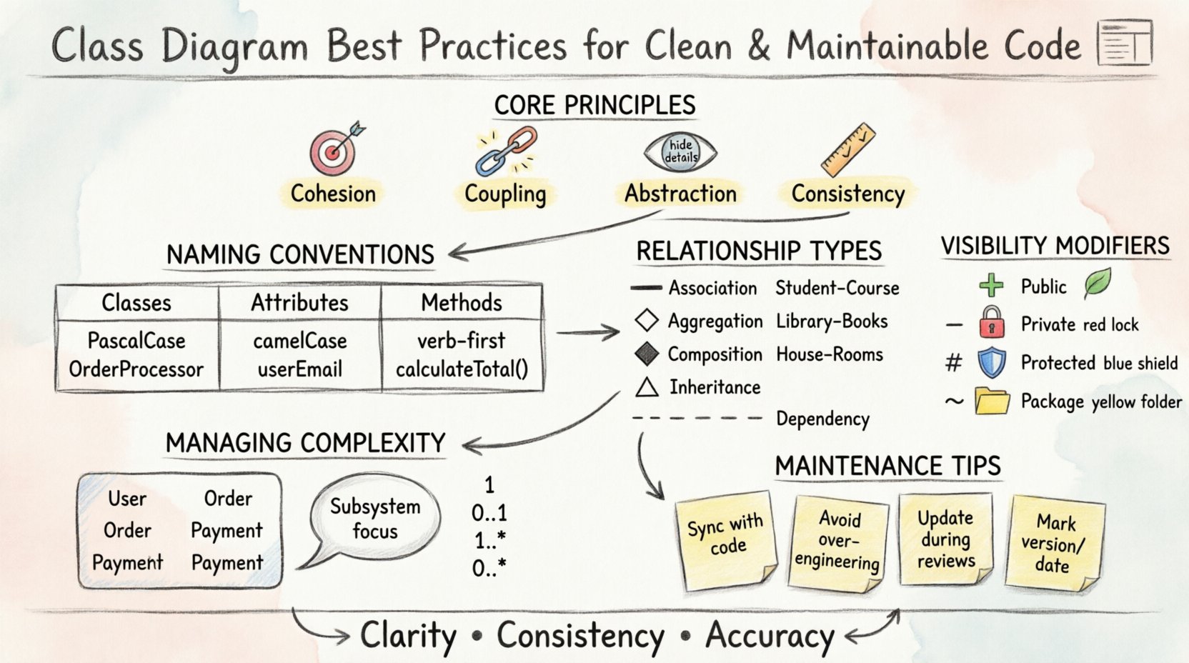
🎯 Core Principles of Effective Design
Before diving into syntax, understanding the underlying principles is essential. These concepts form the foundation of a robust system design. They dictate how classes interact and how information flows through the application.
- Cohesion: A class should have a single, well-defined responsibility. High cohesion means all parts of the class work together to achieve one goal. This makes the class easier to understand and modify.
- Coupling: Minimize dependencies between classes. Low coupling ensures that changes in one area do not cascade unpredictably through the system. Loose coupling allows modules to be replaced or updated independently.
- Abstraction: Expose only what is necessary. Hide internal implementation details behind clear interfaces. This protects the integrity of the data and reduces the risk of external interference.
- Consistency: Use standard naming conventions and notation across all diagrams. Consistency reduces the time required to read and interpret the model.
Violating these principles often leads to spaghetti code or rigid architecture. For example, if a class handles database connections, file I/O, and user interface logic, it violates the Single Responsibility Principle. This makes the class difficult to test and prone to breaking changes.
📝 Naming Conventions and Structure
Naming is the first layer of communication in a diagram. Names should be descriptive and follow established standards. Ambiguous names create confusion and increase the likelihood of errors during implementation.
Class Names
- Use nouns or noun phrases to represent entities.
- Start with a capital letter (PascalCase).
- Be specific. Avoid generic terms like “Manager” or “Handler” unless context is clear.
- Example: Use
OrderProcessorinstead ofProcess.
Attribute Names
- Use camelCase for attribute names.
- Reflect the data type or nature of the value if useful.
- Avoid abbreviations that are not industry standard.
- Example:
userEmailis clearer thanue.
Method Names
- Start with a verb to describe the action.
- Use camelCase.
- Return values should imply success or failure in the name if applicable.
- Example:
calculateTotal()orfetchUserProfile().
Adhering to these conventions helps developers locate definitions quickly. It also aids automated tools in generating code from the model. When names are consistent, the diagram acts as a reliable source of truth.
🔗 Managing Relationships and Dependencies
Relationships define how classes interact. Incorrect modeling of relationships leads to structural flaws in the code. Understanding the nuance between association, aggregation, and composition is vital.
Types of Relationships
Each relationship type conveys a specific level of intimacy and lifecycle dependency between classes.
| Relationship Type | Symbol | Meaning | Use Case |
|---|---|---|---|
| Association | Solid Line | General connection between objects. | A Student enrolls in a Course. |
| Aggregation | Hollow Diamond | Whole-Part relationship; parts can exist independently. | A Library contains Books. Books exist without the Library. |
| Composition | Filled Diamond | Strong ownership; parts cannot exist without the whole. | A House contains Rooms. Rooms do not exist without the House. |
| Inheritance | Triangle Arrow | “Is-a” relationship; child inherits from parent. | ElectricCar extends Car. |
| Dependency | Dashed Line | One class uses another temporarily. | A ReportGenerator uses a DataFormatter. |
Cardinality and Multiplicity
Specify how many instances of a class relate to another. This prevents logical errors in data modeling.
- One-to-One: A single user has exactly one profile.
- One-to-Many: A single author writes many books.
- Many-to-Many: Many students take many courses.
Clearly labeling these constraints on relationship lines prevents ambiguity. Developers need to know if a collection is optional or mandatory. Use notation like 1, 0..1, 1..*, or 0..* to define these bounds precisely.
🔒 Visibility and Encapsulation
Encapsulation is a cornerstone of object-oriented design. It restricts access to components and ensures that internal state is not corrupted by external code. Visibility modifiers must be clearly indicated in the diagram.
Visibility Modifiers
- Public (+): Accessible from any class. Use sparingly for public APIs.
- Private (-): Accessible only within the defining class. Protects internal logic.
- Protected (#): Accessible within the class and its subclasses. Useful for inheritance hierarchies.
- Package (~): Accessible within the same package or module.
Explicitly showing these symbols in the diagram clarifies the intended access control. If a diagram shows all attributes as public, it suggests a lack of encapsulation. This often leads to fragile code where data integrity is hard to enforce.
Interfaces and Abstract Classes
Distinguish between concrete classes and interfaces. Interfaces define contracts without implementation. Abstract classes provide partial implementation.
- Use an interface symbol (often a small circle or stereotype) for pure contracts.
- Mark abstract classes clearly to indicate they cannot be instantiated directly.
- This distinction helps developers understand what they can instantiate and what they must implement.
🧩 Handling Complexity and Scale
As systems grow, a single diagram becomes unmanageable. Cluttered diagrams obscure important details and become difficult to read. Strategies for managing complexity include compartmentalization and abstraction.
Package Diagrams
Group related classes into packages. This logical grouping reduces visual noise. It shows the high-level organization of the system without detailing every class.
- Group classes by functionality (e.g.,
ServiceLayer,DomainModel,Infrastructure). - Use package boundaries to show dependencies between modules.
- Keep package names consistent with directory structures in the codebase.
Subsystems and Focus
Create separate diagrams for specific subsystems. Do not try to fit the entire application into one view. Focus on the area currently under development or analysis.
- Use a Context Diagram to show the system’s relationship with external actors.
- Use Class Diagrams for detailed internal structure.
- Use Component Diagrams for deployment and architectural boundaries.
Decomposing the system allows teams to work on different parts without stepping on each other’s toes. It also makes the diagrams easier to maintain.
🛠️ Maintenance and Evolution
A diagram is not a one-time artifact. It evolves alongside the code. Keeping diagrams synchronized with the implementation is a common challenge. If the diagram diverges from the code, it loses credibility.
Syncing Diagrams with Code
- Update the diagram during code reviews.
- Use round-trip engineering tools if available to regenerate diagrams from code.
- Mark the diagram version or date to track changes over time.
- Review diagrams periodically to remove obsolete classes.
Common Anti-Patterns to Avoid
Certain habits lead to diagrams that fail to provide value. Recognizing these patterns helps in maintaining quality.
| Anti-Pattern | Impact | Mitigation |
|---|---|---|
| Over-Engineering | Diagram is too detailed for the current scope. | Focus on high-level structure first; add detail only when needed. |
| Outdated Models | Diagram does not reflect current code state. | Integrate diagram updates into the CI/CD pipeline. |
| Redundant Classes | Multiple classes perform the same function. | Consolidate functionality into a single class. |
| Missing Relationships | Dependencies are invisible. | Explicitly model all dependencies, even if implicit in code. |
Maintaining a living model requires discipline. It is better to have a simple, accurate diagram than a complex, outdated one. Teams should prioritize accuracy over aesthetics.
📊 Communication and Collaboration
Diagrams are primarily communication tools. They facilitate discussion between developers, stakeholders, and architects. A good diagram conveys information quickly without requiring a deep dive into syntax.
- Stakeholder Alignment: Non-technical stakeholders can understand class structures better than raw code.
- Onboarding: New developers can grasp the system architecture faster with a clear diagram.
- Design Reviews: Diagrams serve as a baseline for architectural discussions.
Ensure the diagrams are accessible to all team members. Store them in a shared repository alongside the code. This ensures everyone is working from the same source of information.
🔍 Implementation Strategy
Integrating these practices into a workflow requires a structured approach. Start by auditing existing diagrams against these principles. Identify areas where naming is inconsistent or relationships are unclear.
- Define Standards: Document naming and modeling conventions for the team.
- Train the Team: Ensure all members understand the UML syntax and best practices.
- Automate Checks: Use tools to validate consistency where possible.
- Iterate: Refine the diagrams as the system evolves.
By following these steps, the team can build a robust foundation for their software projects. The effort invested in modeling pays dividends in reduced bugs and faster development cycles.
🚀 Moving Forward
Clean code begins with clean design. Class diagrams are the visual manifestation of that design. They translate complex requirements into structured components. By applying these best practices, you ensure that your models remain useful assets rather than obsolete documentation.
Focus on clarity, consistency, and accuracy. Treat the diagram as a living document that evolves with the code. This approach fosters a culture of quality and maintainability. The result is a system that is easier to understand, modify, and extend over time.

