


Creating a UML use case diagram is a fundamental step in the software design process. It serves as a bridge between business requirements and technical implementation. However, even experienced analysts often introduce subtle errors that can lead to ambiguity later in development. This guide explores the most frequent pitfalls in use case modeling and provides clear strategies to correct them.
A well-constructed diagram clarifies the scope of a system and identifies how external entities interact with it. When done correctly, it acts as a contract between stakeholders and developers. When done poorly, it becomes a source of confusion and rework. We will examine specific areas where mistakes typically occur, ranging from actor identification to relationship definitions.
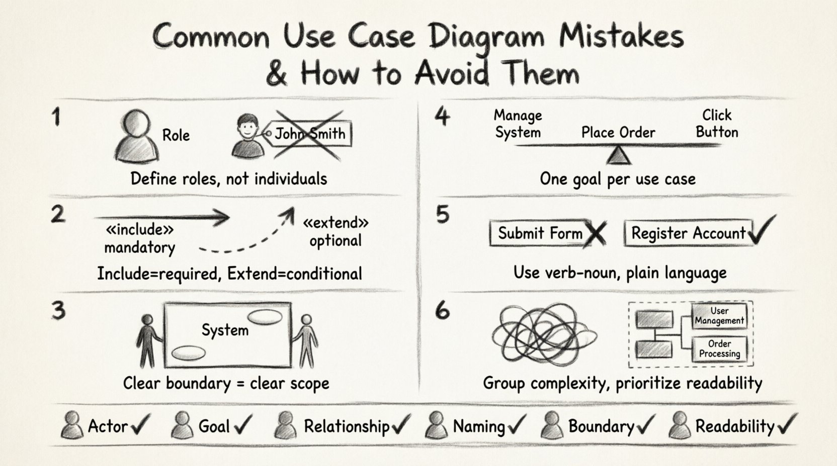
🧐 Mistake 1: Confusing Actors with Users
One of the most prevalent errors involves the definition of an actor. Many designers assume that every person interacting with the system is an actor. This is incorrect. An actor represents a role, not a specific individual. Confusing the two creates rigidity in the design.
- Incorrect Approach: Defining “John Smith” as an actor. If John leaves the company, the diagram must be redrawn.
- Correct Approach: Defining “Sales Manager” as the actor. Any person filling that role is covered.
An actor is an entity outside the system that interacts with it. This entity can be a human, another system, or even a hardware device. The key distinction is that the actor provides input or receives output but does not reside within the system boundary.
Why This Matters
When you model specific people instead of roles, the system design becomes tied to personnel rather than function. If a new employee takes over the “Sales Manager” role, the logic remains the same. If you modeled “John Smith,” the requirements for the system change based on who is holding the position.
- Scalability: Role-based actors allow the system to scale without changing the diagram.
- Clarity: Stakeholders understand their responsibilities better when roles are defined.
🔗 Mistake 2: Misusing «include» and «extend» Relationships
Relationships define the behavior flow between use cases. The arrows labeled «include» and «extend» are often swapped or applied incorrectly. These relationships have distinct semantic meanings that affect the logic of the system.
Understanding «include»
The «include» relationship indicates that one use case must involve the behavior of another. It is mandatory. The base use case delegates specific behavior to the included use case to reduce duplication.
- Example: A “Withdraw Money” use case includes “Verify PIN”. You cannot withdraw money without verifying the PIN.
- Direction: The arrow points from the base use case to the included use case.
Understanding «extend»
The «extend» relationship indicates optional behavior. It occurs under specific conditions. The extending use case adds functionality to the base use case but is not required for the base use case to complete.
- Example: A “Place Order” use case may be extended by “Apply Coupon”. The order can be placed without a coupon.
- Direction: The arrow points from the extending use case to the base use case.
Common Confusion
Designers often use «include» for optional steps or «extend» for mandatory steps. This reverses the logic of the system flow. If a step is mandatory, it belongs in the main flow or via «include». If it is situational, use «extend».
📦 Mistake 3: Ignoring System Boundaries
The system boundary is the rectangle that separates the internal processes from external actors. A common mistake is drawing this boundary loosely or inconsistently. This leads to ambiguity about what the system does and what the environment does.
- Boundary Creep: Including processes that should be external. For example, “Payment Processing” should be inside if the system handles it. If it calls an external bank API, the bank is an actor.
- Missing Boundaries: Failing to draw a box around the use cases. This makes the diagram look like a list of tasks rather than a system model.
A clear boundary helps stakeholders understand the scope of the project. Anything outside the box is out of scope for the current development cycle.
🔍 Mistake 4: Inconsistent Granularity
Granularity refers to the level of detail in a use case. A diagram should not mix high-level goals with low-level system steps. If one use case is “Manage System” and another is “Click Button A”, the diagram is confusing.
Too High Level
Use cases like “Manage System” are too broad. They do not describe a specific interaction goal. Stakeholders cannot validate requirements against a vague goal.
Too Low Level
Use cases like “Display Login Screen” are too detailed. These are UI actions, not system functions. They clutter the diagram and hide the actual business value.
The Golden Rule
Each use case should represent a discrete unit of value that provides a complete result to an actor. It should be a verb-noun phrase that describes a goal. For example, “Place Order” is a goal. “Enter Order Details” is a step within that goal.
🏷️ Mistake 5: Poor Naming Conventions
Names are the primary way to communicate meaning in a diagram. If names are inconsistent or vague, the diagram fails to serve as documentation. Avoid using technical jargon or internal database terms.
- Bad: “Submit Form” (Which form? Why?)
- Good: “Register Account” (Clear goal)
Use the verb-noun structure consistently. Verb indicates the action, noun indicates the object. This makes the diagram readable for non-technical stakeholders.
🎨 Mistake 6: Visual Clutter and Over-connection
A diagram with too many lines crossing each other is hard to read. This often happens when trying to show every possible interaction in a single view. While completeness is good, readability is essential.
If a diagram becomes too dense, consider breaking it down into subsystems or using inheritance to group similar actors. Do not force all relationships into one box. A diagram is a communication tool, not a database dump.
📊 Summary of Common Errors
| Mistake | Why It Fails | Correction Strategy |
|---|---|---|
| Modeling People instead of Roles | Diagram becomes outdated when staff changes | Define actors by job function or system interface |
| Swapping Include and Extend | Logic flow becomes invalid or confusing | Use Include for mandatory, Extend for optional |
| Vague System Boundaries | Scope is unclear to stakeholders | Draw a clear box and keep external entities outside |
| Mixing Granularity Levels | Diagram is unreadable and inconsistent | Ensure all use cases represent full user goals |
| Technical Naming | Business stakeholders cannot understand | Use natural language verb-noun phrases |
| Excessive Lines | Visual noise hides important relationships | Use packages or sub-diagrams to group complexity |
🛡️ Best Practices for Clean Modeling
To ensure your diagrams remain effective throughout the project lifecycle, adhere to these foundational principles.
- Start with Goals: Ask “What does the user want to achieve?” before drawing any boxes.
- Validate with Stakeholders: Walk through the diagram with business users. If they do not recognize their workflow, the model is flawed.
- Iterate: Use case diagrams are not static. Update them as requirements evolve. Do not treat the diagram as a one-time deliverable.
- Keep it Simple: If a diagram exceeds one page, consider splitting it. Complex systems often require multiple diagrams for different modules.
- Focus on Value: Every use case should deliver value to an actor. If a use case does not provide a result, question its existence.
🔄 The Lifecycle of a Use Case
Understanding the lifecycle helps in identifying where mistakes often creep in. The process moves from conceptualization to detailed specification.
1. Identification
Gather requirements. Identify who interacts with the system and what they do. This is the raw data phase.
2. Modeling
Translate the raw data into the UML notation. Define the actors, the system boundary, and the relationships. This is where the mistakes discussed above typically occur.
3. Validation
Review the model. Check for consistency. Ensure the logic holds up against real-world scenarios. Are there dead ends? Are there missing paths?
4. Implementation
Developers use the diagram to understand the requirements. If the diagram is ambiguous, the code will likely be incorrect. Clear diagrams reduce development errors.
🧩 Handling Complex Systems
When dealing with large enterprise systems, a single use case diagram is rarely sufficient. The complexity can overwhelm the viewer. In these cases, grouping is essential.
Use packages to group use cases by business domain. For example, a “Billing” package and a “Inventory” package. This allows you to show the high-level interaction without drowning the viewer in details. You can still maintain a master diagram that links to the detailed sub-diagrams.
Additionally, consider using generalization. If you have multiple actors that perform similar tasks, such as “Admin” and “Manager,” you can create a parent actor “Administrator” and inherit the relationships. This reduces redundancy and clarifies that these roles share core capabilities.
⚠️ What Happens When You Ignore These Mistakes?
Ignoring modeling errors has tangible consequences. It is not just about a pretty picture. The diagram drives the development.
- Rework: Developers build features that do not match the requirements because the use case was ambiguous.
- Missed Requirements: If a relationship is missed, a feature might be forgotten entirely.
- Communication Breakdown: If stakeholders do not understand the diagram, they cannot approve the requirements.
- Maintenance Costs: A messy diagram is hard to update. Future developers will hesitate to change the code if the design documentation is unclear.
📝 Final Checklist for Review
Before finalizing your diagram, run through this checklist to ensure quality.
- Actor Check: Are all actors outside the system boundary?
- Goal Check: Does every use case achieve a specific goal for an actor?
- Relationship Check: Are «include» and «extend» used correctly?
- Naming Check: Are all names clear, concise, and consistent?
- Boundary Check: Is the system boundary clearly drawn?
- Readability Check: Is the diagram easy to follow without excessive line crossings?
By adhering to these standards, you ensure that your use case diagrams serve their true purpose: clear communication and accurate requirements definition. This attention to detail saves time and resources in the long run. Focus on accuracy over speed, and the quality of your design will reflect that effort.

