


Software systems are becoming increasingly intricate. As projects grow, the architecture must evolve to maintain clarity and manageability. This is where Component Diagrams for Modular Design come into play. They provide a structured way to visualize the high-level organization of a system without getting bogged down in implementation details.
When dealing with large-scale applications, understanding how pieces fit together is crucial. A component diagram offers a blueprint for the system’s building blocks. It focuses on the interfaces, dependencies, and relationships between modules. This approach supports system decomposition and helps teams manage complexity effectively.
What is a Component Diagram? 🔍
In the context of the Unified Modeling Language (UML), a component diagram is a type of structural diagram. It describes the organization and wiring of physical or logical software components. Unlike a class diagram, which details internal implementation, a component diagram abstracts the system into black boxes.
Each box represents a component. Inside this box, you find the internal structure, but the focus is on the external contract. This separation allows developers to work on modules independently. It defines what a component does, not exactly how it does it.
Key Characteristics
- Abstraction: Hides internal logic behind defined interfaces.
- Reusability: Components are designed to be swapped or reused across projects.
- Independence: Changes in one component should not break others, provided interfaces remain stable.
- Deployment Context: Can show how components map to physical hardware or deployment nodes.
Core Elements of a Component Diagram 🧩
To build a meaningful diagram, you need to understand the specific symbols and notation used. These elements form the vocabulary of modular design.
1. Components
A component is a modular part of a system. It encapsulates state and behavior. Visually, it looks like a rectangle with two small tabs on the left side.
- Logical Components: Represent libraries, packages, or microservices.
- Physical Components: Represent executables, databases, or files.
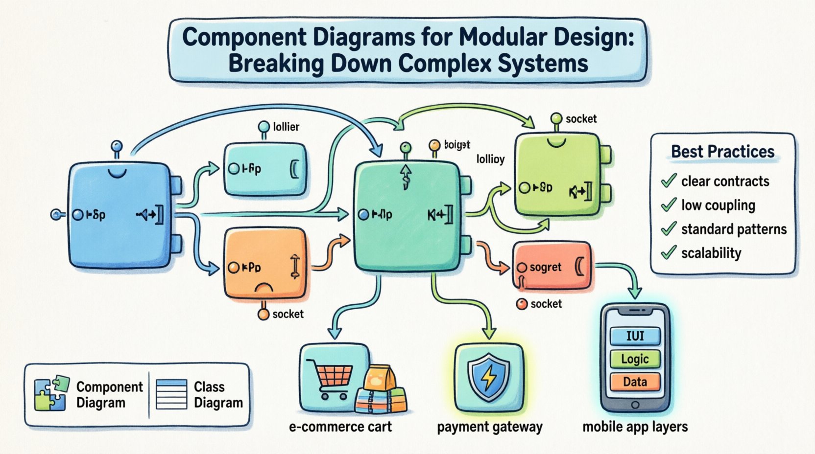
2. Interfaces
Interfaces are the points of interaction. They define the contract between components. There are two main types:
- Provided Interfaces: What the component offers to the outside world. Often shown as a “lollipop” symbol.
- Required Interfaces: What the component needs to function. Often shown as a “socket” symbol.
3. Ports
Ports are the specific locations where connections are made. They act as the entry and exit points for messages or data. A component can have multiple ports, each associated with a specific interface.
4. Connectors
Connectors represent the relationships between components. They link the provided interface of one component to the required interface of another. This defines the flow of control and data.
Why Use Component Diagrams for Modular Design? 🚀
Modular design is about breaking a large problem into smaller, manageable parts. Component diagrams support this by visualizing the boundaries and interactions.
Benefits of This Approach
- Improved Maintainability: Teams can update specific modules without affecting the whole system.
- Parallel Development: Different teams can work on different components simultaneously.
- Clear Documentation: Provides a high-level overview for stakeholders and new developers.
- Dependency Management: Makes it easy to identify circular dependencies or tight coupling.
- Technology Agnostic: Focuses on structure rather than specific programming languages.
Component vs. Class Diagrams 📊
It is common to confuse component diagrams with class diagrams. While both are structural, they serve different purposes. Understanding the distinction is vital for effective architecture.
| Feature | Component Diagram | Class Diagram |
|---|---|---|
| Level of Abstraction | High-level, macro view | Low-level, implementation detail |
| Focus | Modules and interfaces | Classes, attributes, and methods |
| Change Frequency | Changes rarely, stable | Changes frequently, volatile |
| Primary Use | System architecture | Code structure and logic |
| Reusability | Designed for reuse | Designed for specific tasks |
Designing for Modularity: Best Practices 🛠️
Creating a diagram is not enough. You must apply principles that ensure the resulting system is robust. Here are strategies to guide the design process.
1. Define Clear Contracts
Interfaces should be explicit. Avoid hidden dependencies. If a component needs a database, it should request the database interface, not create a connection directly inside its logic. This ensures flexibility.
2. Minimize Coupling
Coupling refers to the degree of interdependence between software modules. Low coupling is preferred. Use dependency injection or message passing to reduce direct links.
- High Cohesion: Keep related functions within the same component.
- Low Coupling: Keep components independent of each other.
3. Use Standard Patterns
Leverage established architectural patterns. Examples include layered architecture, microkernel, or pipe-and-filter. These provide a proven structure for component interaction.
4. Plan for Scalability
Design components to handle growth. A component that works for 100 users should be designed to work for 100,000. Consider how components will be replicated or distributed.
Common Pitfalls to Avoid ⚠️
Even experienced architects make mistakes. Being aware of common errors helps you refine your diagrams.
- Over-Engineering: Creating too many small components can be just as bad as having one giant one. Find the right granularity.
- Ignoring Interfaces: Focusing only on internal logic without defining how the outside world connects.
- Static Dependencies: Hard-coding connections between components makes the system rigid and hard to test.
- Ignoring Lifecycle: Forgetting how components are deployed, started, and stopped.
Step-by-Step Guide to Creating a Diagram 📝
Follow these steps to construct a meaningful component diagram for your project.
Step 1: Identify Core Functions
Start by listing the main capabilities of the system. What are the primary goals? Group these functions into logical domains.
Step 2: Define Components
Map the functions to components. Each component should have a single responsibility. Give each a clear name that reflects its role.
Step 3: Specify Interfaces
For each component, list what it provides and what it requires. Be specific about data types and operation signatures.
Step 4: Draw Connections
Link the components using connectors. Ensure that every required interface has a corresponding provided interface nearby. Check for orphaned interfaces.
Step 5: Review and Refine
Walk through the diagram with the team. Ask if the boundaries make sense. Is it easy to understand the flow of data? Adjust as necessary.
Advanced Concepts: Deployment and Configuration 🔧
Component diagrams can go beyond software logic. They can also represent physical deployment.
Deployment Nodes
You can map components to physical devices. This is useful for distributed systems. For example, a “Payment Component” might reside on a secure server, while a “User Interface Component” runs in a browser.
Configuration Management
Components often rely on external configurations. Document how these settings are injected. This ensures consistency across environments like development, staging, and production.
Managing Component Dependencies 🔄
Dependencies are the lifelines of a system. However, they can also become tangled webs. Managing them is critical.
Dependency Inversion
High-level modules should not depend on low-level modules. Both should depend on abstractions. This allows you to swap out implementations without rewriting the core logic.
Versioning
Components will evolve. Plan for versioning your interfaces. If a change is breaking, create a new interface version rather than modifying the existing one.
Real-World Application Scenarios 💼
How does this apply to actual projects? Let’s look at a few contexts.
- E-Commerce Platforms: Separate the shopping cart, payment gateway, and inventory management into distinct components.
- Enterprise Systems: Break down the system into modules for HR, Finance, and Supply Chain.
- Mobile Applications: Isolate the UI layer from the data access layer to allow for different device support.
Integration with Other Diagrams 🤝
A component diagram does not exist in isolation. It works alongside other UML diagrams.
- Use Case Diagrams: Define the requirements that components must fulfill.
- Sequence Diagrams: Show the dynamic interaction between components over time.
- Class Diagrams: Provide the detailed structure within each component.
Documentation and Maintenance 📖
A diagram is only useful if it stays up to date. Outdated diagrams can lead to confusion and errors.
Keep It Current
Update the diagram whenever the architecture changes. Treat it as living documentation.
Centralize Storage
Store diagrams in a version control system. This allows you to track changes over time and revert if necessary.
Accessibility
Ensure all team members can access the diagrams. Use a shared repository or documentation platform.
Conclusion on Modular Architecture 🏁
Building complex systems requires a disciplined approach to design. Component diagrams are a powerful tool for this discipline. They clarify boundaries, define contracts, and guide implementation.
By focusing on modularity, teams can create systems that are easier to understand, maintain, and extend. The effort put into designing clear components pays off in long-term stability. Whether you are starting a new project or refactoring an old one, this approach provides a solid foundation.
Remember that the goal is clarity. If a diagram is too complex, simplify it. If it is too vague, add detail. Strive for the balance that best serves your specific context. With careful planning and adherence to best practices, modular design will serve your system well for years to come.

