


In the complex world of software architecture, communication is often as critical as the code itself. The C4 context diagram stands as the first level of the C4 model hierarchy, designed specifically to provide a high-level overview of a software system and its place in the world. As a foundational tool for software architecture communication, it helps teams visualize the scope of their system and its interactions with various stakeholders and external entities.
This guide will walk you through the process of understanding, planning, and generating C4 context diagrams, utilizing modern AI-powered tools from Visual Paradigm to streamline the workflow.
Step 1: Understand the Level 1 Abstraction
Before drawing any boxes or lines, it is essential to understand the philosophy behind the C4 context diagram. It is strictly Level 1 of the C4 hierarchy. This means you must resist the urge to document internal technical details like containers, components, or code classes.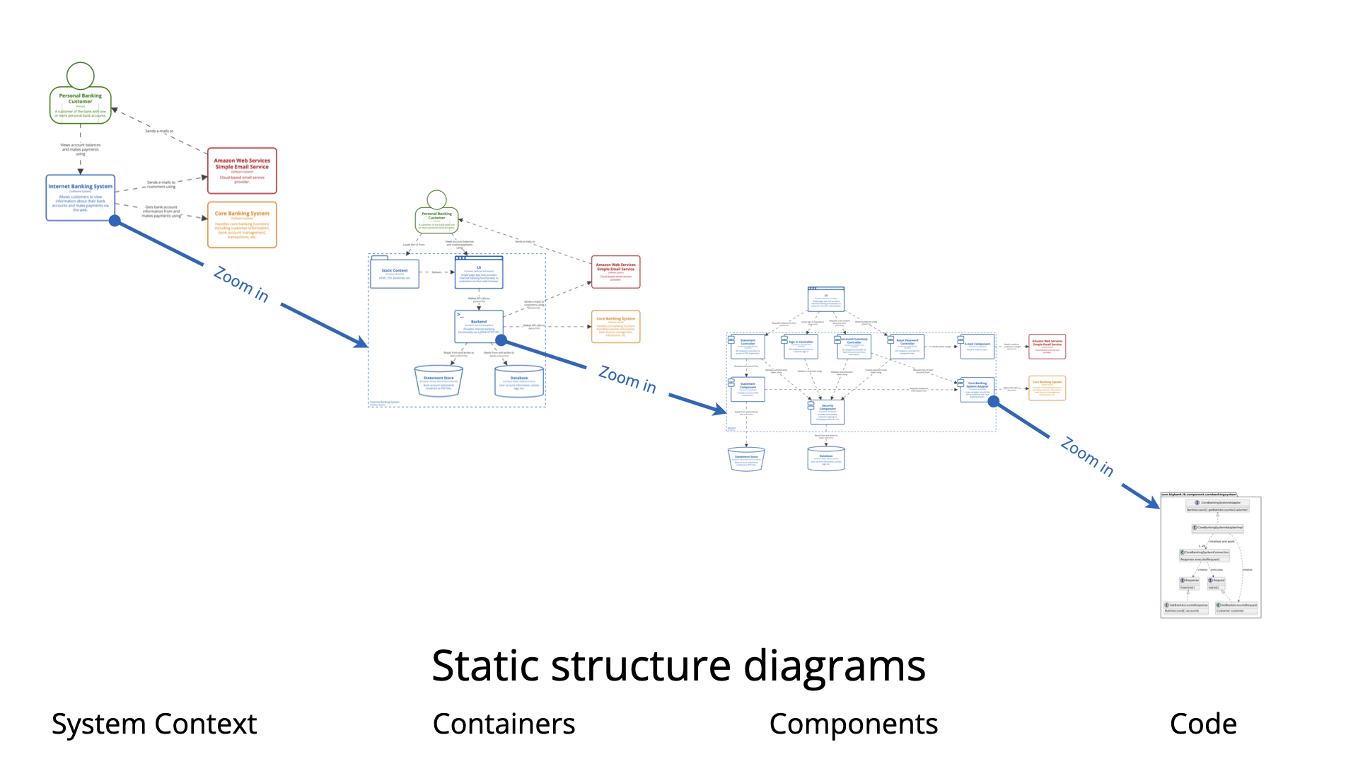
Focus on the concept of System Abstraction. Your primary goal is to capture the “big picture.” Imagine explaining the system to a non-technical stakeholder; you would describe what the system does and who uses it, rather than how it works internally.
The “Black Box” Approach
Adopt the “Black Box” mindset. The system you are modeling should be represented as a single box at the center of the diagram. Treat its internal workings as hidden. Your focus must remain strictly on external interfaces and boundaries.
Step 2: Identify the Actors and Systems
Once you have established the scope, you need to identify the entities that surround your central system. These generally fall into two categories:
- People (Actors): These are the specific roles or users who interact with the system. For example, in a retail system, this might include “Customer” or “Admin.”
- Software Systems: These include both the system you are building and any external systems it relies on. External systems are critical for showing dependencies, such as payment gateways, email services, or legacy mainframes.
Step 3: Map Out Interactions with Practical Scenarios
To ensure your diagram is accurate, it helps to map out specific scenarios. Strategic planning during this phase is vital for communicating system design to both technical and non-technical stakeholders.
Consider these standard examples to guide your thinking:
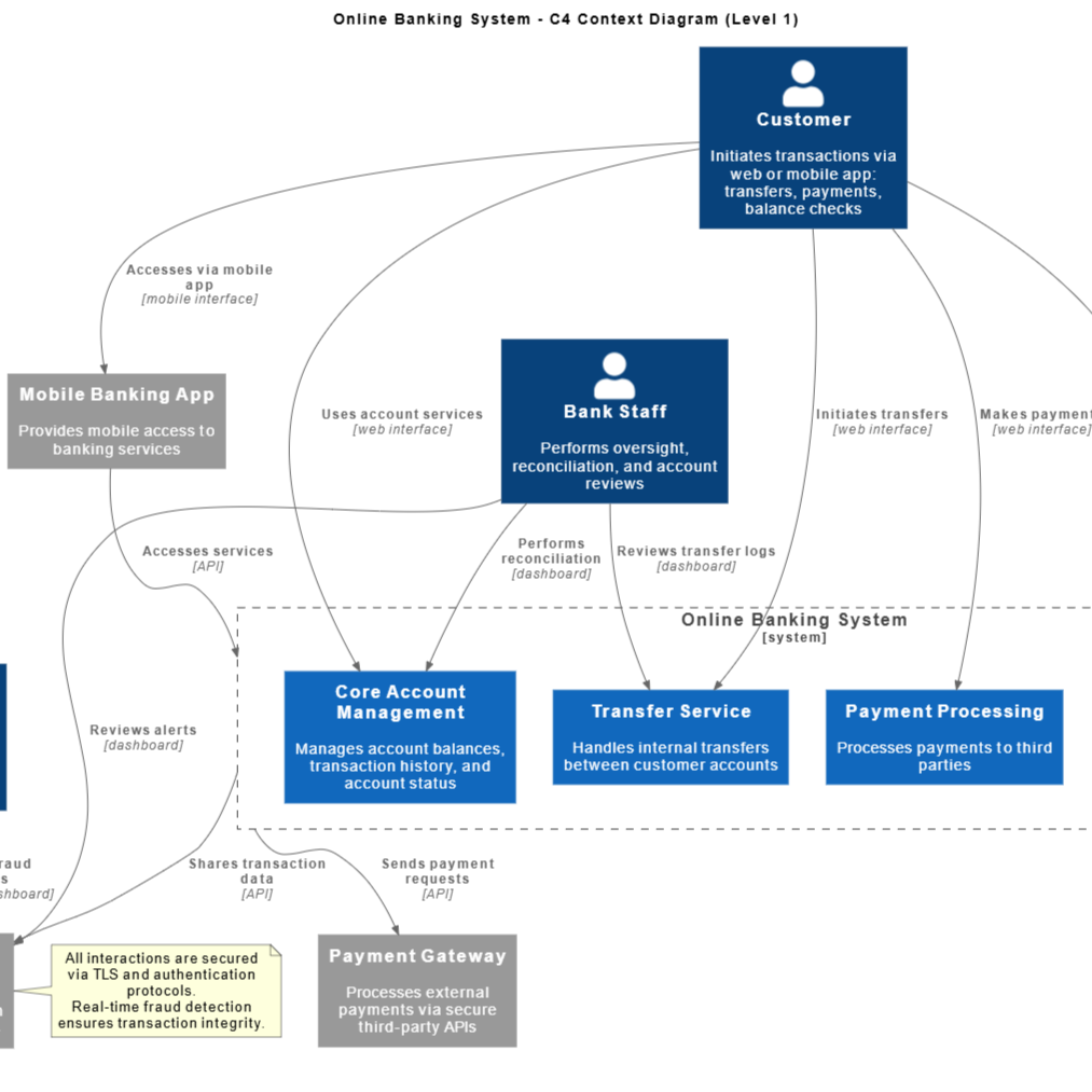
- Internet Banking System: Place the banking application at the center. Draw connections to “Personal Banking Customers” (People), “External Mainframe Systems” (Software System), and “Email Services” (Software System).
- Car Park Booking System: Illustrate how a “Driver” interacts with the system to book a spot, and how the system communicates vertically with external “Payment Gateways” or physical “Monitoring Hardware.”
- API-Driven Applications: Use the diagram to define the boundaries where third-party services consume data from your central system.
Step 4: Automate Creation with Visual Paradigm AI
Traditionally, drawing these diagrams required manual drag-and-drop tools. However, you can now accelerate this process using the Visual Paradigm AI Platform.
Option A: Text-to-Diagram Generation
If you have a written specification, use the AI-Powered C4 PlantUML Studio. This tool allows you to transform simple natural language descriptions into accurate, layered C4 diagrams. By inputting your scenario (e.g., “A banking system connecting to a user and a mainframe”), the AI generates the necessary PlantUML code and visual output instantly.
Option B: Interactive Modeling with Chatbots
For a more iterative approach, utilize the Visual Paradigm AI Chatbot. This chatbot acts as a virtual modeling partner. You can provide prompts explaining your intent, and the AI will interpret them to generate presentation-ready diagrams. This is particularly useful for brainstorming sessions where requirements are evolving.
Step 5: Refine, Collaborate, and Integrate
A diagram is rarely finished in the first draft. The final step involves refinement and integration into the broader architectural documentation.
- Context-Aware Refinement: Use the AI tools to refine existing models. The AI can intelligently update diagrams based on new instructions—such as adding a new user type or external API—while preserving existing naming conventions and structural integrity.
- Collaborative Design: Leverage the Visual Paradigm Circle platform to co-create models in real time. You can share your context diagram via a URL to get instant feedback from your team.
- Integrated Modeling: Ensure modeling continuity. Link your high-level C4 context diagram directly to deeper levels (like containers and components) within the platform to maintain a seamless architectural thread.
By following these steps and leveraging AI automation, you can produce clear, professional C4 context diagrams that effectively align development teams and business stakeholders.
Visual Paradigm’s c4 and AI Powered C4 Resource
The following articles and resources provide detailed information on utilizing AI-powered tools for creating, generating, and refining C4 model diagrams within the Visual Paradigm platform:
-
C4-PlantUML Studio | AI-Powered C4 Diagram Generator – Visual Paradigm: This AI-powered tool automatically generates C4 software architecture diagrams from simple text descriptions.
-
AI Diagram Generator: Complete C4 Model Support: This release introduces an AI-powered diagram generator in Visual Paradigm for automatically creating C4 model diagrams.
-
Visual Paradigm Full C4 Model Support Release: The platform provides full support for creating and managing C4 architecture diagrams at multiple abstraction levels using artificial intelligence.
-
The Ultimate Guide to C4-PlantUML Studio: Revolutionizing Software Architecture Design: This guide explains how the C4-PlantUML Studio combines AI-driven automation with PlantUML’s flexibility to streamline architecture design.
-
A Comprehensive Guide to Visual Paradigm’s AI-Powered C4 PlantUML Studio: This studio transforms natural language into accurate and layered C4 diagrams for complex system visualization.
-
Leveraging Visual Paradigm’s AI C4 Studio for Streamlined Architecture Documentation: Designers can use the AI-enhanced C4 Studio to create clean, scalable, and maintainable software architecture documentation.
-
Comprehensive Tutorial: Generating and Modifying C4 Component Diagrams with Visual Paradigm AI Chatbot: This tutorial demonstrates using an AI-powered chatbot to generate and refine C4 component diagrams for specific use cases like a car park booking system.
-
C4 Model AI Generator: Automate Context – Ez Knowledge: The Visual Paradigm AI Chatbot uses conversational prompts to automate the full lifecycle of C4 modeling for development teams.
-
AI-Powered C4 Diagram Generator – Visual Paradigm AI: This generator supports documentation for the four core levels of the C4 model including context, container, component, and deployment views.
-
C4 Diagram Tool by Visual Paradigm – Visualize Software Architecture with Ease: Visual Paradigm’s C4 diagram tool enables software architects to create clear, scalable, and maintainable system diagrams.
-
C4 Diagram Solution by Visual Paradigm – Enterprise-Grade Architecture Visualization: This solution supports standardized, hierarchical modeling for improved communication and clarity in software systems.
-
Beginner’s Guide to C4 Model Diagrams – Visual Paradigm Blog: This guide provides a step-by-step introduction to creating C4 model diagrams across all four levels of abstraction for effective communication.
-
C4 Model Tool – Visual Paradigm: This tool enables developers and architects to create and manage C4 diagrams for visualizing software architecture at multiple levels of abstraction.