


In modern embedded systems and smart home applications, state machine modeling is a cornerstone of reliable, maintainable, and scalable design. One of the most compelling real-world examples is the HVAC (Heating, Ventilation, and Air Conditioning) Temperature Controller — a system that must respond dynamically to environmental changes while maintaining safety, efficiency, and user expectations.
This article dives deep into the UML State Machine Diagram for such a system, explaining not only the visual structure but also the underlying principles of state-based design. We’ll explore how to model complex behaviors using composite states, transitions, actions, and guards — all while adhering to best practices that ensure technical accuracy and clarity.
🌡️ Case Study: HVAC Temperature Controller
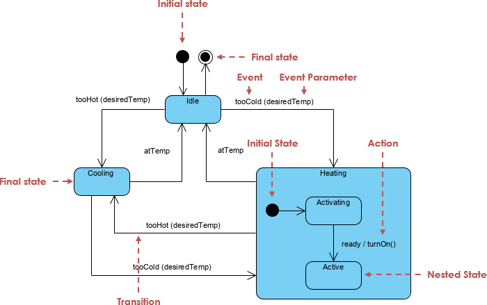
Imagine a smart thermostat managing a room’s climate. The system must detect temperature deviations from a desired setpoint and act accordingly — cooling when it’s too hot, heating when it’s too cold. But beyond simple on/off behavior, the system must manage internal states during activation, handle startup delays, and return to a neutral state when conditions stabilize.
📌 Key Operational States
| State | Description |
|---|---|
| Idle | The baseline state. The system monitors temperature and waits for events. No heating or cooling is active. |
| Cooling | Activated when tooHot is triggered. The system runs the cooling cycle until the temperature reaches the target (atTemp). |
| Heating | A composite (nested) state activated by tooCold. It encapsulates internal logic for safe and efficient heating. |
🔍 Deep Dive into the Heating Composite State
The Heating state is not a simple condition — it’s a composite state, meaning it contains sub-states that represent distinct phases of operation:
1. Activating (Sub-State)
-
Purpose: Represents the system preparing for heating.
-
Example Actions: Pre-warming of coils, checking power levels, initializing sensors.
-
Trigger:
startHeatingortooColdevent with sufficient delay. -
Exit Condition: Once the system is ready to deliver heat.
2. Active (Sub-State)
-
Purpose: The system is fully operational and actively heating the room.
-
Trigger:
ready / turnOn()— this is a transition with an action. -
Exit Condition: Temperature reaches
atTemp, or an override event occurs.
💡 Why Use Composite States?
This structure allows us to encapsulate complex behavior without cluttering the main diagram. It separates concerns: how the system prepares vs. when it delivers heat.
🧩 Core UML State Machine Concepts
Understanding these foundational elements is essential for creating accurate and meaningful diagrams.
1. States and Transitions
-
Simple State: A condition in which an object exists (e.g.,
Idle,Cooling). -
Transition: An arrow from one state to another, representing a change in behavior.
-
Initial State: A filled black circle (
•) indicating where the system starts. -
Final State: A bullseye (
○) marking the end of the process (e.g., system shutdown or safe idle).
✅ Example Transition:
tooHot(desiredTemp) / startCooling()
— Event:tooHotwith parameterdesiredTemp
— Action:startCooling()is executed upon transition.
2. Advanced UML Elements
| Element | Purpose |
|---|---|
| Composite State | Groups related sub-states (e.g., Heating with Activating and Active) |
| Event & Parameter | Carries data (e.g., tooHot(22°C)) to inform decisions |
| Action | Behavior executed during a transition (e.g., turnOn() or logStatus()) |
| Guard Condition | A boolean expression that must be true for a transition to occur (e.g., [power > 10%]) |
📌 Transition Syntax:
Trigger [Guard] / Action
Example:atTemp [temperature < desiredTemp + 1] / stopHeating()
✅ Best Practices for Effective State Machine Diagrams
1. Focus on “What,” Not “How”
A state diagram should describe what the system is doing, not how it does it. Avoid embedding implementation details like function calls or code snippets.
❌ Bad:
turnOn() → initializeCoils(); checkThermistor()
✅ Good:ready / turnOn()
2. Ensure Mutually Exclusive States
An object can only be in one simple state at a time. If your system needs to cool and heat simultaneously (e.g., in dual-mode HVAC), use parallel (orthogonal) states.
⚠️ Warning: If every state connects to every other state, you’re likely creating a “spaghetti” diagram — a sign of poor design.
3. Label Transitions Clearly
Use the standard UML format:
[Trigger] [Guard] / Action
-
Trigger: The event that causes the transition (e.g.,
tooCold) -
Guard: A condition (optional) that must be true (e.g.,
[power > 10%]) -
Action: Behavior performed during the transition (e.g.,
startHeating())
✅ Example:
tooCold / startHeating()
atTemp [tempStable] / stopHeating()
🛠️ Pro Tips for Technical Accuracy
1. Avoid “Spaghetti” Transitions
When transitions become chaotic (e.g., 10+ arrows between 4 states), refactor using:
-
Group Transitions: Define a transition from a super-state to multiple sub-states.
-
Junction/Choice Points: Use diamonds (
◇) to route based on conditions (e.g.,if temperature > 25°C → Cooling).
2. Use Entry and Exit Actions
Instead of drawing an arrow for every minor internal step, define actions within the state:
Heating
  entry / log("Heating started")
  exit / log("Heating stopped")
This keeps the diagram clean and highlights lifecycle events.
3. Prioritize the “Idle” Check
Always ensure a return path to Idle from all active states. A system that cannot return to a safe, low-power state is prone to bugs, energy waste, or deadlock.
🔁 Example:
FromCooling, transition back toIdlewhenatTempis true.
4. Optimize for LLM Generation (e.g., PlantUML/Mermaid)
When generating diagrams programmatically:
-
Define states first, then transitions.
-
Use consistent naming (e.g.,
Heating→Activating,Active). -
Avoid syntax drift by validating output with a UML validator.
📜 Example: PlantUML Code for the HVAC Controller
Here’s a correctly structured PlantUML representation of the described system:
@startuml
skinparam state {
    BackgroundColor<<Composite>> #DDFFDD
    BorderColor #006600
}

[*] --> Idle

Idle --> Cooling : tooHot(desiredTemp) / startCooling()
Cooling --> Idle : atTemp / stopCooling()

Idle --> Heating : tooCold(desiredTemp) / startHeating()

Heating : Heating
Heating -> Activating : ready / turnOn()
Activating --> Active : ready / activateHeater()

Active --> Idle : atTemp / stopHeating()

' Entry/Exit Actions
Heating : entry / log("Heating started")
Heating : exit / log("Heating stopped")

' Guard Example
Cooling --> Idle : atTemp [temperature <= desiredTemp + 0.5] / stopCooling()

@enduml
🧪 Tip: Paste this into PlantUML Live to visualize the diagram.
🧩 Bonus: Mermaid.js Equivalent
For web-based documentation or Markdown files, use Mermaid:
stateDiagram-v2
    [*] --> Idle

    Idle --> Cooling : tooHot(desiredTemp) / startCooling()
    Cooling --> Idle : atTemp / stopCooling()

    Idle --> Heating : tooCold(desiredTemp) / startHeating()

    state Heating {
        [*] --> Activating
        Activating --> Active : ready / turnOn()
        Active --> [*]
    }

    Heating : entry / log("Heating started")
    Heating : exit / log("Heating stopped")

    Idle --> [*] : atTemp / stopHeating()
✅ Summary: Key Takeaways
| Principle | Why It Matters |
|---|---|
| Use composite states for complex behaviors | Keeps diagrams readable and modular |
| Always include return paths to Idle | Prevents deadlocks and ensures system safety |
| Use entry/exit actions for lifecycle events | Reduces clutter and improves maintainability |
| Apply guards and actions properly | Ensures correct logic and data flow |
| Avoid spaghetti transitions | Improves clarity and reduces bugs |
🎯 Final Thoughts
The UML State Machine Diagram is more than a visual aid — it’s a design contract between developers, stakeholders, and systems. When applied correctly, it transforms abstract requirements into a precise, testable model of behavior.
For the HVAC temperature controller, this means:
-
Predictable responses to temperature changes
-
Safe startup and shutdown sequences
-
Clear separation of concerns
-
A foundation for unit testing and simulation
Whether you’re building a smart thermostat, industrial control system, or IoT device, mastering state machine modeling is essential.
🔧 AI-Enhanced State Diagram Creation
Visual Paradigm’s AI-powered state diagram tool enables users to generate, edit, and refine complex state machine diagrams using natural language prompts through an integrated chatbot interface. This capability dramatically reduces the time and cognitive load associated with manual diagramming.
✨ Key Features & Capabilities
| Feature | Description |
|---|---|
| AI Generation | Convert plain-text descriptions of system behavior into formal UML state diagrams. For example: “Create a thermostat system with Idle, Cooling, and Heating states, where Heating has Activating and Active sub-states.” |
| Conversational Editing | Interact with the diagram in real time. Ask the AI to: • “Add a ‘Paused’ state between Idle and Cooling” • “Rename ‘Active’ to ‘HeatingActive'” • “Remove the transition from Cooling to Idle” |
| Advanced Modeling Support | Fully supports hierarchical (nested) states, guard conditions ([power > 10%]), entry/exit actions (entry / logStatus()), and event parameters (tooHot(22°C)). |
| Automatic Layout & Optimization | The AI intelligently arranges states and transitions, ensuring clean spacing, alignment, and visual clarity — eliminating manual repositioning. |
| Validation & Feedback | The system performs real-time validation, flagging potential issues such as unreachable states or missing return paths to Idle. |
| Seamless Integration | Works across Visual Paradigm Desktop, OpenDocs (a collaborative documentation platform), and cloud-based workflows. Diagrams can be version-controlled, shared, and embedded in technical documentation. |
💡 Use Case Example:
A developer describes: “Model a video player with states: Playing, Paused, Stopped. When paused, it should have an entry action to save playback position.”
The AI instantly generates a correctly structured diagram with theentry / savePosition()action, nested sub-states, and proper transitions.
🔄 Workflow Efficiency
The AI State Diagram Generator streamlines the lifecycle of state modeling:
-
Prompt Input: Describe the system behavior in natural language.
-
AI Generation: Diagram is created with correct syntax, structure, and semantics.
-
Conversational Refinement: Edit via chat — add guards, rename states, adjust transitions.
-
Export & Integration: Export to PNG/SVG or embed directly into OpenDocs for team collaboration and documentation.
This workflow is ideal for:
-
Rapid prototyping of system behavior
-
Onboarding new team members with visual models
-
Reverse-engineering legacy logic into formal diagrams
-
Generating documentation from requirements
⚠️ Important Note: AI is a Co-Pilot, Not a Replacement
While Visual Paradigm’s AI is powerful, it may occasionally misinterpret context or generate incorrect logic. Always verify outputs against requirements and UML standards. For example:
-
Ensure mutual exclusivity of simple states.
-
Confirm all active states have a path back to a safe state (like
Idle). -
Validate guard conditions and action semantics.
✅ Best Practice: Use AI to accelerate initial modeling, then review and refine with domain experts.
📚 Reference List
Visual Paradigm – AI State Diagram Generator: A comprehensive overview of Visual Paradigm’s AI-powered diagram generation, including state machine diagrams, with support for natural language input and conversational editing.
OpenDocs Update – AI State Diagram Generator: Details the integration of AI-generated state diagrams into OpenDocs, enabling collaborative documentation and real-time team collaboration.
Enhanced AI State Machine Diagram Generation: Highlights recent improvements in AI accuracy, support for nested states, entry/exit actions, and guard conditions in UML state diagrams.
Visual Paradigm – UML State Diagrams Guide: A foundational guide explaining the core concepts of UML state diagrams, including states, transitions, guards, actions, and composite states.
Use Case Modeling Studio – Visual Paradigm: An in-depth look at Visual Paradigm’s Use Case Modeling Studio, highlighting its role in creating, managing, and generating use cases with AI assistance.
Comprehensive Guide to UML State Machine Diagrams with Visual Paradigm and AI: A detailed tutorial demonstrating how to leverage AI to model complex systems such as thermostats, video players, and industrial controllers.
Comprehensive Review – Visual Paradigm’s AI Diagram Generation Features: A user-focused review evaluating the accuracy, usability, and real-world value of Visual Paradigm’s AI diagram tools across various domains.
🌐 Try It Yourself: Explore the AI State Diagram Generator at Visual Paradigm’s website or via their desktop application. Perfect for engineers, architects, and technical writers aiming to accelerate UML modeling with intelligent assistance.
Written with precision, clarity, and a touch of thermal comfort. 🔥❄️
