


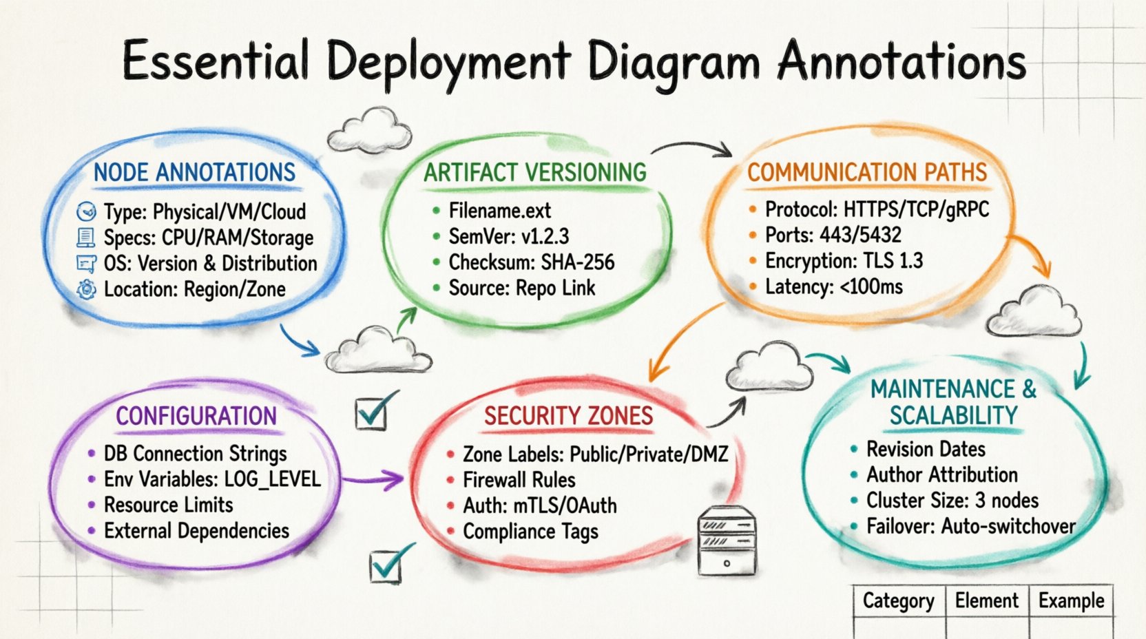
A deployment diagram serves as the architectural blueprint for your software infrastructure. It visualizes how software artifacts are physically realized on hardware nodes within a system. Without precise annotations, this diagram becomes a mere sketch rather than a functional document for engineers and operations teams. Clarity in these diagrams reduces ambiguity during the deployment phase and prevents costly errors in production environments. This guide explores the critical elements that must be annotated to ensure a deployment diagram is actionable, accurate, and maintainable over time.
Understanding Node Annotations 🖥️
The foundation of any deployment diagram is the node. Nodes represent the physical or virtual computing resources where software components reside. A node without proper annotation is indistinguishable from any other piece of hardware, making it impossible to configure the environment correctly. When annotating nodes, you must specify the type of resource it represents. This includes distinguishing between physical servers, virtual machines, cloud instances, or specialized devices like load balancers and routers.
Consider the following critical details that should be annotated for every node:
- Node Type: Clearly label whether the node is a physical machine, a container host, or a cloud instance.
- Hardware Specifications: Include CPU cores, RAM capacity, and storage type (SSD vs. HDD) if performance is a constraint.
- Operating System: Specify the OS version and distribution, as this impacts software compatibility and security patches.
- Location: Indicate the physical or logical location, such as a specific data center, region, or availability zone.
For example, a node labeled simply “Server” provides no utility. A node labeled “Application Server (Ubuntu 22.04 LTS, 8 vCPU, 32GB RAM, us-east-1)” provides the necessary context for the DevOps team to provision the infrastructure. This level of detail ensures that the deployment process aligns with the architectural requirements and avoids compatibility issues during runtime.
Artifact Identification and Versioning 📦
Artifacts are the physical representations of software components, such as executables, libraries, configuration files, and containers. Each artifact must be linked to a specific node, and that link requires annotation. Without this, the diagram fails to communicate what is actually being deployed to the infrastructure. An artifact annotation should include the filename, the version number, and the checksum or hash to verify integrity.
When documenting artifacts, ensure the following information is present:
- Filename: The exact name of the deployable file, including extensions.
- Version Number: Semantic versioning (e.g., v1.2.3) allows teams to track changes and roll back if necessary.
- Checksum: A cryptographic hash ensures the file has not been corrupted or tampered with during transfer.
- Source Repository: Link to the repository where the artifact was built to facilitate traceability.
Imagine a scenario where a deployment fails because the wrong version of a library was used. If the diagram clearly annotated “LibraryA-v2.0.1 (sha256:abc123…)”, the engineer could immediately verify if the artifact on the node matched the specification. This level of granularity is crucial for audit trails and compliance requirements in regulated industries.
Communication Paths and Protocols 📡
Nodes do not exist in isolation; they communicate over networks. The lines connecting nodes represent communication paths, and these lines require robust annotations to define how data flows between components. A simple line is insufficient. You must specify the protocol, the port numbers, and the encryption status of the connection.
Key annotations for communication paths include:
- Protocol: Define the communication standard, such as HTTP, HTTPS, TCP, UDP, or gRPC.
- Port Numbers: Specify the source and destination ports to avoid conflicts and ensure firewall rules are correct.
- Encryption: Indicate if the traffic is encrypted (TLS/SSL) or transmitted in plain text.
- Latency Constraints: If the path has strict timing requirements, annotate the maximum allowed latency.
For instance, a connection between a web server and a database server must be annotated with “TCP Port 5432, Encrypted (TLS 1.3)”. Without the port number, the firewall configuration team would have to guess, leading to blocked traffic. Without the encryption status, the security team might miss a vulnerability. These annotations bridge the gap between design and implementation.
Configuration Parameters and Environment Variables ⚙️
Software behavior is often dictated by configuration parameters and environment variables. These settings determine how an application behaves in its specific environment. A deployment diagram is the ideal place to capture these static configurations so that the infrastructure matches the application expectations. Annotating configuration details prevents the “it works on my machine” syndrome.
Include the following configuration annotations:
- Database Connection Strings: Annotate the host, database name, and authentication method (do not include passwords).
- Environment Variables: List critical variables like LOG_LEVEL, CACHE_TTL, or FEATURE_FLAGS.
- Resource Limits: Specify memory limits or CPU quotas assigned to the node or container.
- External Dependencies: Note the URLs or endpoints for external services the node relies on.
Consider a microservices architecture where one service depends on an external payment gateway. If the diagram does not annotate the gateway URL and the required API key prefix, the deployment script might fail silently or use a default endpoint. Annotating these parameters ensures that the environment is configured consistently across development, staging, and production.
Security Zones and Boundary Annotations 🔒
Security is a non-negotiable aspect of modern architecture. Deployment diagrams often visualize security boundaries, such as firewalls, DMZs, and trusted zones. These boundaries must be explicitly annotated to define which nodes are exposed to the public internet and which are restricted to internal networks. Failing to annotate security zones can lead to accidental exposure of sensitive internal services.
Essential security annotations include:
- Zone Names: Label areas like “Public Zone”, “Private Zone”, or “Management Zone”.
- Firewall Rules: Indicate which traffic is allowed or denied between zones.
- Authentication Methods: Specify how nodes authenticate with each other (e.g., mTLS, OAuth tokens).
- Compliance Tags: Mark nodes that handle sensitive data and require specific compliance standards.
A diagram that lacks security annotations is a liability. For example, if a database node is drawn next to a web server without a firewall boundary annotation, an engineer might assume they are on the same network segment. This assumption could lead to a security breach. Clearly marking the perimeter ensures that network engineers implement the correct segmentation policies.
Maintaining Diagram Accuracy 🔄
A deployment diagram is a living document. As infrastructure evolves, the diagram must be updated to reflect changes. Annotations should include a version or revision history to track when specific elements were modified. This helps teams understand the evolution of the system and diagnose issues that arose from configuration drift.
Best practices for maintaining annotations include:
- Revision Dates: Add a date to each major annotation change.
- Author Attribution: Note who made the change for accountability.
- Change Log: Maintain a separate log linked to the diagram that explains the reason for the change.
- Deprecation Markers: Clearly mark components that are scheduled for removal to prevent accidental reuse.
When a new server is added to a cluster, the diagram should be updated immediately. If the annotation for the new node is missing, future engineers might not know its role, leading to misconfiguration. Regular updates ensure the diagram remains a reliable source of truth throughout the software lifecycle.
Comprehensive Annotation Reference Table 📊
To assist in quickly referencing the necessary details, the following table summarizes the essential annotations categorized by their function within the deployment diagram.
| Category | Annotation Element | Purpose | Example Value |
|---|---|---|---|
| Node | Type | Identify hardware role | Load Balancer |
| Node | OS | Define compatibility | Linux Kernel 5.10 |
| Artifact | Version | Track releases | v3.5.1 |
| Artifact | Checksum | Verify integrity | SHA-256: a1b2c3… |
| Connection | Protocol | Define communication | HTTPS |
| Connection | Port | Configure networking | 443 |
| Config | Environment | Set runtime behavior | DB_HOST=internal |
| Security | Zone | Define boundaries | DMZ |
Impact of Missing Annotations ⚠️
The absence of these annotations creates technical debt. When a diagram lacks detail, the burden of discovery falls on the engineer who is trying to deploy the system. This leads to increased time spent on debugging, higher risk of human error, and potential security vulnerabilities. Teams often have to reverse-engineer the infrastructure from the running system rather than following a plan.
Common consequences of poor annotation include:
- Deployment Failures: Scripts fail because expected ports or paths were not documented.
- Security Gaps: Open ports are left exposed due to missing firewall annotations.
- Version Conflicts: Incompatible software versions are deployed because versioning was not specified.
- Onboarding Delays: New team members cannot understand the architecture without detailed labels.
Investing time in thorough annotation during the design phase saves significant resources during the execution phase. It transforms the diagram from a passive illustration into an active tool for deployment automation and infrastructure management.
Scalability and Redundancy Considerations 📈
Modern systems require scalability and redundancy. The deployment diagram must reflect how the system handles growth and failures. Annotations should indicate clustering configurations and failover mechanisms. This helps operations teams understand how the system behaves under load.
Annotations for scalability include:
- Cluster Size: State the number of nodes in a cluster (e.g., “3 Node Cluster”).
- Replication Factor: Specify how many copies of a service are active.
- Failover Strategy: Describe what happens if a node goes down (e.g., “Automatic Switchover”).
- Auto-scaling Rules: Note the conditions that trigger adding or removing nodes.
Without these annotations, a system designed for high availability might be deployed as a single point of failure. Annotating the redundancy strategy ensures that the infrastructure supports the business continuity requirements.
Finalizing Your Diagram Documentation ✅
A well-annotated deployment diagram is the cornerstone of reliable software delivery. It connects the logical design to the physical reality. By focusing on node types, artifact versions, communication protocols, and security zones, you create a document that serves both developers and operations staff. Regular reviews of these annotations keep the documentation aligned with the actual infrastructure.
When you next create a deployment diagram, take the time to review each element against the checklist provided in this guide. Ensure every node has a type and location. Verify every artifact has a version. Confirm every connection has a protocol and port. This diligence pays off in smoother deployments, fewer incidents, and a more resilient system architecture.
Remember that the goal is clarity. If an annotation requires explanation, add a legend or a reference note. Avoid ambiguity at all costs. Your future self and your team will thank you for the precision you put into these diagrams today.

