


Business Process Model and Notation (BPMN) serves as the industry standard for visualizing business processes. It provides a graphical notation that is easily understood by all business stakeholders, from analysts to developers. Understanding the different diagram types within BPMN 2.0 is crucial for accurate process mapping, analysis, and automation. This guide explores the specific diagram categories, their distinct purposes, and the elements that compose them.
Understanding the Core Building Blocks 🧱
Before diving into specific diagram types, it is essential to understand the fundamental elements that make up any BPMN diagram. These building blocks create the visual language used to describe workflows.
Events 🟢
Events represent something that happens during a process. They are depicted as circles and are categorized by their timing and function:
- Start Event: Indicates where a process begins. It is usually a thin-bordered circle.
- End Event: Marks the termination of a process. It is a thick-bordered circle.
- Intermediate Event: Occurs between the start and end. These can signal a delay, a message receipt, or an error.
Activities ⚙️
Activities represent work performed within a process. They are shown as rounded rectangles:
- Task: The smallest unit of work. It is an atomic action with no internal sub-process.
- Sub-Process: A collection of tasks grouped together. This can be collapsed (showing only the container) or expanded (showing internal details).
- Call Activity: References a process defined elsewhere, allowing for reuse without duplication.
Gateways 🚦
Gateways control the divergence and convergence of sequence flows. They determine the logic of the process:
- Exclusive Gateway: Represents a decision point where only one path is taken (XOR).
- Parallel Gateway: Splits the flow into multiple simultaneous paths (AND).
- Inclusive Gateway: Allows for one or more paths to be taken based on conditions (OR).
- Event-Based Gateway: Waits for specific events to occur before proceeding.
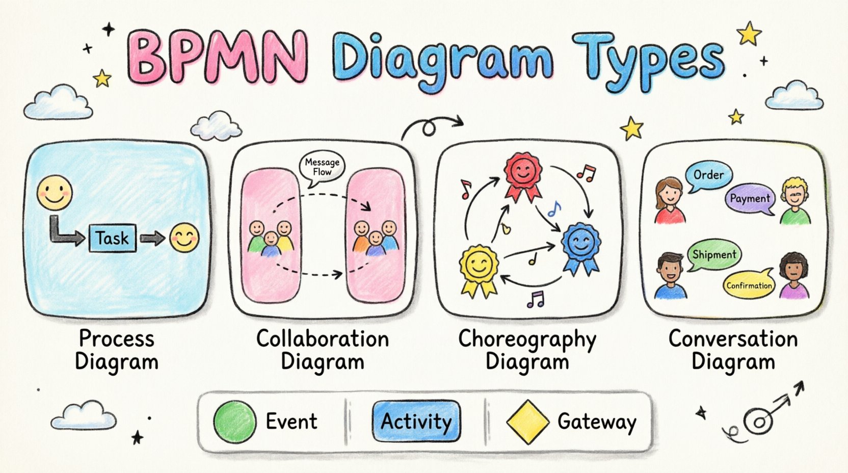
The Four Main BPMN Diagram Categories 🗺️
BPMN is not a monolith; it is a suite of diagram types designed for different modeling needs. Each type serves a specific scope regarding visibility and interaction.
1. Process Diagram (Private vs. Public) 🔄
This is the most common type of BPMN diagram. It focuses on the internal logic of a specific process.
- Private Process: Shows the internal logic of a single participant. It includes details that might not be visible to external parties, such as internal database updates or decision logic.
- Public Process: Also known as a Choreography diagram in some contexts, this shows only the parts of the process that are visible to other participants. Internal steps are hidden.
These diagrams utilize Pools and Swimlanes to organize activities by role or system.
2. Collaboration Diagram 🤝
A Collaboration diagram describes the interaction between multiple participants. It is often used to model high-level business interactions between different organizations or departments.
- Multiple Pools: Unlike a standard process diagram which might focus on one pool, a collaboration diagram displays several pools side-by-side.
- Message Flows: The primary connector here is the Message Flow, indicated by a dashed arrow. This shows information passing between participants.
- Visibility: It abstracts away internal logic to focus on communication.
3. Choreography Diagram 💃
Choreography diagrams focus on the exchange of messages between participants without detailing the internal logic of each participant. It answers the question: “What messages need to be exchanged to complete this interaction?”
- No Internal Logic: You will not see tasks or gateways inside the participants. Instead, you see interaction nodes.
- Interaction Nodes: These represent the specific message exchanges (Send/Receive) between roles.
- Role Definition: Roles are defined within the diagram, often represented by triangles or specific shapes indicating who initiates the message.
4. Conversation Diagram 💬
Conversation diagrams provide a high-level view of a conversation between participants. They map out the participants and the topics of conversation without detailing the sequence of messages.
- Conversation Nodes: Represent a specific topic or topic of conversation.
- Participants: Show which entities are involved in the conversation.
- Use Case: Useful for defining the scope of a discussion before diving into the detailed message flow.
Pools and Swimlanes Explained 🏊
Organizational structure is critical in BPMN diagrams. Pools and Swimlanes provide the framework for assigning responsibility.
Pools 🏊♂️
A Pool represents a participant in a process. This could be a company, a department, or an external system.
- Boundary: The pool acts as a container for the process elements.
- Separation: Different pools indicate different boundaries of control. A process inside one pool cannot directly affect another pool without a message flow.
- Labeling: Pools are typically labeled with the name of the participant.
Swimlanes 🏊♀️
Swimlanes divide a pool into subcategories, usually representing roles, departments, or systems within the same participant.
- Vertical or Horizontal: Swimlanes can run either vertically or horizontally across the diagram.
- Responsibility: They clarify who is responsible for a specific task. For example, a “Finance” swimlane might contain approval tasks, while a “Sales” swimlane contains order entry tasks.
- Readability: They help readers quickly identify which part of the organization executes a specific step.
Choosing the Right Diagram Type 🤔
Selecting the correct diagram type depends on the goal of the modeling effort. Below is a comparison to assist in decision-making.
| Diagram Type | Primary Focus | Key Connector | Best Used For |
|---|---|---|---|
| Process Diagram | Internal Logic | Sequence Flow | Executing a single workflow, automation, detailed analysis. |
| Collaboration Diagram | Inter-Organization Interaction | Message Flow | Mapping hand-offs between departments or external partners. |
| Choreography Diagram | Message Exchange | Message Flow (Interaction) | Defining API contracts or service interactions without internal logic. |
| Conversation Diagram | Topics of Discussion | Conversation Link | High-level scoping of multi-party discussions. |
Best Practices for Modeling 🛠️
To ensure diagrams are effective, adhere to these structural guidelines.
Consistency in Notation 🎨
- Use standard shapes for all elements. Do not create custom icons for standard tasks.
- Ensure line styles are consistent. Sequence flows should be solid arrows; message flows should be dashed arrows.
- Keep font sizes uniform to maintain a clean appearance.
Clarity in Flow 🧭
- Avoid crossing lines. If lines must cross, use a bridge symbol to indicate they do not intersect.
- Ensure all gateways have matching pairs. If a flow splits at a gateway, it must eventually merge back at a corresponding gateway.
- Label all sequence flows with conditions (e.g., “Yes” or “No”) near exclusive gateways.
Granularity Control 📏
- Do not model every single click or micro-action. Focus on business-level steps.
- Use sub-processes to hide complexity. If a section of the process is too detailed for the main view, encapsulate it in a collapsed sub-process.
- Maintain a logical level of abstraction appropriate for the audience.
Common Pitfalls to Avoid 🚫
Even experienced modelers can fall into traps that reduce the utility of the diagrams.
Overcomplicating the Logic
Attempting to model every possible edge case in a single diagram makes it unreadable. Use decision tables or external documentation for complex logic rules.
Mixing Flows
Do not mix Sequence Flows and Message Flows within the same pool incorrectly. Sequence flows stay within a pool; Message Flows cross between pools.
Ignoring Event Types
Using a generic start event when a specific event (like a timer or message) is required can lead to confusion about how the process is triggered.
Reading the Flow: Sequence vs. Message 📡
Understanding the difference between these two flow types is fundamental to BPMN syntax.
Sequence Flow 🟦
- Definition: Shows the order of activities within a single participant.
- Symbol: Solid line with a filled arrowhead.
- <Scope: Internal to the pool.
Message Flow 🟨
- Definition: Shows communication between participants.
- Symbol: Dashed line with an open arrowhead.
- Scope: Between pools.
Conclusion and Next Steps 🚀
BPMN offers a robust framework for documenting business processes. By selecting the appropriate diagram type and adhering to standard notation, you create artifacts that facilitate communication and execution. Whether you are modeling a simple approval chain or a complex multi-party integration, the structure provided by BPMN ensures clarity and precision.
Start by mapping your core processes using standard Process Diagrams. As complexity increases, explore Collaboration and Choreography diagrams to manage interactions. Consistent application of these standards will improve the quality of your process documentation and support more effective operational analysis.

