


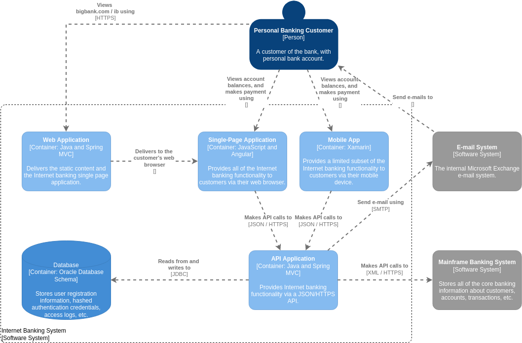
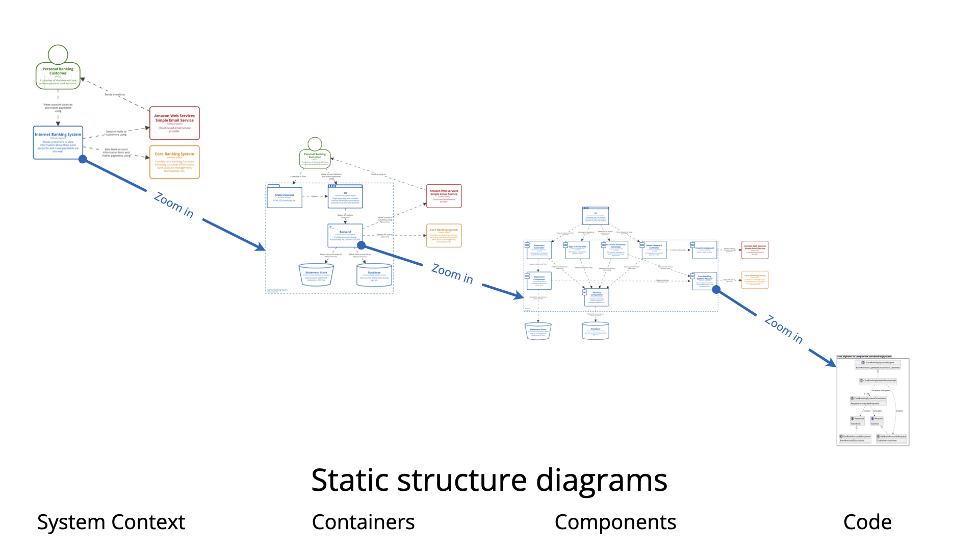
The C4 model has become a standard in software architecture for its ability to visualize systems through a hierarchical lens, focusing on Context, Containers, Components, and Code. However, while these core levels excel at mapping the static structure of a system—showing what exists and how it is organized—they often encounter limitations when describing complex operational logic or runtime environments. To bridge the gap between static definitions and dynamic reality, architects must rely on supplementary diagrams. These diagrams capture the dynamic behavior, runtime interactions, and physical deployment strategies that the standard C4 hierarchy cannot fully articulate.
The Necessity of Supplementary Diagrams
The primary strength of the C4 model is its ability to reduce complexity by abstracting details at different levels of zoom. However, a map of structural elements often lacks the narrative required to explain how those elements interact over time. Standard C4 diagrams focus on the “what,” often leaving a gap in explaining complex operational logic or how a system transitions between different states.
Supplementary diagrams introduce the behavioral dimension to architectural documentation. By visualizing the flow of data, the timing of requests, and the changing states of entities, these diagrams allow teams to identify undefined execution paths or logic errors early in the design phase, long before code is written.
Key Supplementary Views in the C4 Ecosystem
To create a holistic view of software architecture, specific supplementary diagrams are utilized alongside the core C4 views. These are chosen based on the specific dimension of the system that needs to be clarified.
UML State Machine Diagrams
When a specific component possesses complex internal logic or operates through multiple distinct phases, a UML State Machine diagram is essential. Unlike a component diagram that simply shows connections, this view details how an entity responds to events through specific transitions and actions.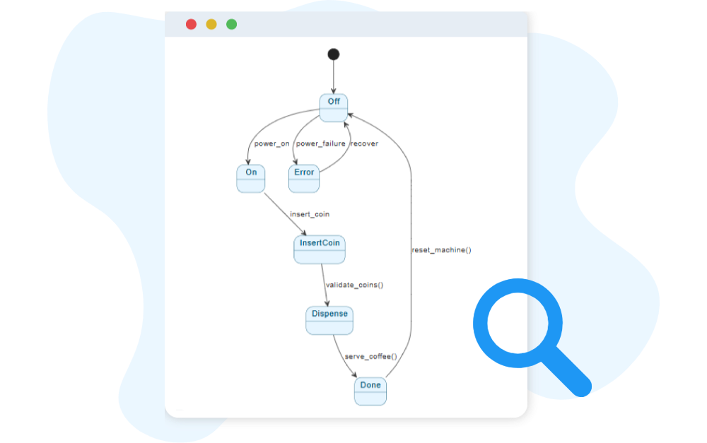
Use Case: These are particularly useful for systems with high logic variability, such as an automated toll system or the control software for a 3D printer. The diagram maps every possible state the system can inhabit and the triggers required to move from one state to another.
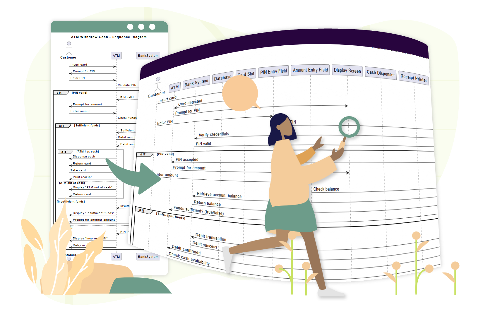
UML Sequence Diagrams
While static maps show that two containers communicate, they rarely explain the nuance of that communication. UML Sequence Diagrams are used to visualize the timing and order of messages exchanged between containers or components during a specific scenario. They provide a chronological view of interactions, making them ideal for detailing runtime behavior that is too intricate for a static map to convey.
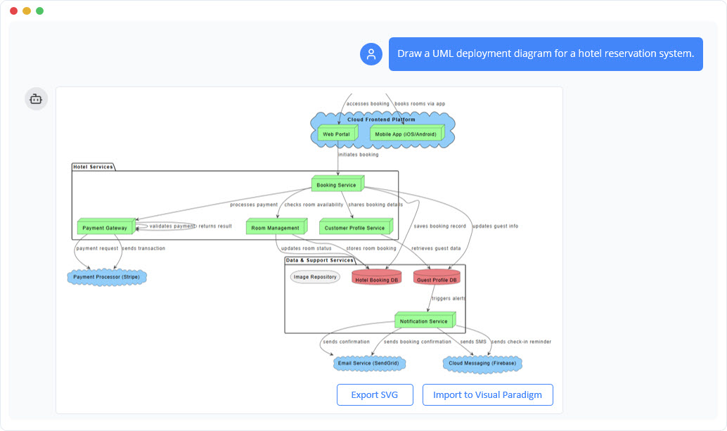
C4 Deployment Diagrams
Software does not exist in a vacuum; it requires infrastructure. C4 Deployment Diagrams map the physical architecture of the system, illustrating how software containers and components are deployed onto infrastructure nodes. This includes mapping code to specific cloud instances, physical servers, or container orchestration platforms like Kubernetes.
Dynamic Diagrams
Dynamic diagrams act similarly to sequence diagrams but are often less formal. They focus specifically on runtime interactions at the container or component level, visualizing how a specific request—such as a user login or a payment transaction—flows through the system elements defined in the static C4 maps.
Balancing the Documentation: Mandatory vs. Optional
In the C4 methodology, not every diagram is required for every project. Understanding what is mandatory versus what is optional ensures that documentation remains valuable without becoming burdensome.
- Mandatory: The Context, Container, and Component levels are widely considered the baseline requirement. They provide the necessary context for stakeholders and developers to understand the system’s boundaries and high-level technical building blocks.
- Optional: The Code level (Level 4) is frequently omitted because code changes too rapidly for diagrams to keep up, unless a specific module is exceptionally complex. Similarly, supplementary behavioral diagrams (like State or Sequence) are optional. They are typically reserved for areas where the risk of misunderstanding logic is high, ensuring effort is spent where it delivers the most clarity.
How to Select the Right Diagram
Choosing the correct supplementary view depends entirely on the specific architectural challenge that needs to be communicated. Architects should use the following decision framework:
- For Infrastructure Challenges: If the goal is to show where code physically lives or how resources are allocated, choose a Deployment Diagram.
- For Timing and Communication: If the difficulty lies in understanding the chronological flow of messages between services, choose a Sequence Diagram.
- For Logic and Process: If the risk involves state-dependent behavior or complex rules, choose a State Machine Diagram to map every transition and prevent design errors.
- For Modularity: If the focus is strictly on dependencies and module organization, stick to the core Component Diagram.
Maintaining consistency across these various views is critical. By utilizing all-in-one modeling platforms like Visual Paradigm AI, architects can ensure modeling continuity. This allows high-level C4 containers to be linked directly to the behavioral state or sequence diagrams that define their internal workflows, creating a seamless and navigable architectural documentation suite.
The following articles and resources provide detailed information on using AI-powered tools to create and refine C4 models and UML component diagrams within the Visual Paradigm platform:
-
Major Upgrade to AI UML Component Diagram Generation in Visual Paradigm AI Chatbot: The Visual Paradigm AI Chatbot now offers advanced capabilities for generating UML component diagrams directly from natural language prompts.
-
AI-Powered Component Diagrams with Visual Paradigm Chatbot: This tool simplifies the creation of component diagrams by transforming natural language descriptions into precise, ready-to-use models.
-
Comprehensive Tutorial: Generating and Modifying C4 Component Diagrams with Visual Paradigm AI Chatbot: This tutorial demonstrates how to use the AI-powered chatbot to generate and refine C4 component diagrams for specific use cases like a car park booking system.
-
AI-Powered C4 Diagram Generator – Visual Paradigm AI: The AI-powered generator supports documentation for the four core levels of the C4 model, including context, container, component, and deployment views.
-
The Ultimate Guide to C4-PlantUML Studio: Revolutionizing Software Architecture Design: This guide explores how C4-PlantUML Studio combines AI-driven automation with PlantUML’s flexibility to streamline software architecture design.
-
A Comprehensive Guide to Visual Paradigm’s AI-Powered C4 PlantUML Studio: This guide describes how the studio transforms natural language input into accurate and layered C4 diagrams for complex system visualization.
-
C4 Model AI Generator: Automate Context: The Visual Paradigm AI Chatbot uses conversational prompts to automate the full lifecycle of C4 modeling for development teams.
-
AI-Generated UML Component Diagrams: Artificial intelligence assistance enables the accurate and efficient creation of UML component diagrams for modern software design.
-
Why Every Team Needs an AI Diagram Maker for Faster Project Kickoff: This article explains how AI-powered modeling tools accelerate project initiation by automating the creation of UML and component diagrams.
-
AI Diagram Generator: Complete C4 Model Support: This release introduces an AI-powered generator that enables the automatic creation of diagrams based on the C4 model.
-
Visual Paradigm Full C4 Model Support Release: Visual Paradigm provides full support for creating and managing C4 architecture diagrams at multiple abstraction levels using artificial intelligence.
-
UML Component Diagram Tutorial and Tool – Visual Paradigm: This resource provides an interactive guide for using AI tools to model system architecture and various component relationships.