


Business processes drive organizational value, yet they often fail due to unclear documentation. When stakeholders, developers, and analysts disagree on a workflow, the result is rework, budget overruns, and delayed delivery. The core issue frequently lies in fixing ambiguity in requirement gathering diagrams. While Business Process Model and Notation (BPMN) offers a standard visual language, it is not immune to misinterpretation. A diagram is only as good as the clarity of its symbols and the precision of its logic.
This guide addresses how to eliminate confusion in process modeling. We will explore common pitfalls, establish validation standards, and ensure that every diagram communicates intent without doubt. By focusing on precision, teams can reduce the friction between design and execution.
📋 Why Ambiguity Occurs in BPMN Modeling
Even with a standardized notation like BPMN, human interpretation varies. A symbol that represents a decision for one person might represent a check for another. Ambiguity often stems from mixing natural language requirements with visual symbols without sufficient context.
Common sources of confusion include:
- Overloaded Symbols: Using complex tasks to represent simple data checks without explanation.
- Inconsistent Naming: Calling the same activity “Review” in one place and “Approval” in another.
- Missing Context: Failing to specify what triggers a process or what constitutes a successful end state.
- Implicit Logic: Assuming the reader knows the business rules behind a gateway decision.
When requirements are vague, the diagram becomes a source of debate rather than a blueprint. Fixing this requires a shift from drawing shapes to defining logic.
🚫 Common Pitfalls in Process Modeling
Certain modeling patterns frequently introduce uncertainty. Recognizing these traps is the first step toward clarity. Below are the most frequent errors found in requirement diagrams.
1. The Gateway Confusion
Gateways control flow, but they are often misused. A Exclusive Gateway (diamond with an X) implies only one path is taken. A Parallel Gateway (diamond with a +) implies all paths run simultaneously. Confusion arises when:
- Gateways are used without explicit condition labels.
- Parallel branches merge without a corresponding merge gateway.
- The logic for a decision is documented in a text box far from the symbol.
Every path leaving a decision point must have a condition. If no condition is visible, the modeler must assume a default path, which leads to errors.
2. Event-Based Gateways
Event-based gateways allow a process to wait for an external trigger. These are often misunderstood because the timing is uncertain. A process might wait for a payment confirmation OR a cancellation request. If the timeout duration is not defined, the process hangs indefinitely. Ambiguity here creates technical debt because the system must handle edge cases that were not modeled.
3. Task Granularity
Tasks should represent a single unit of work. If a task says “Process Order,” it hides complexity. Does it involve checking stock? Calculating tax? Updating the CRM? If a task is too broad, the analyst and the developer will implement different levels of detail. Specificity is required to prevent scope creep.
✅ Strategies for Clarity and Precision
Eliminating ambiguity requires a disciplined approach to modeling. The goal is to make the diagram self-explanatory. The following strategies help enforce this standard.
1. Standardize Naming Conventions
Consistency reduces cognitive load. Adopt a rule where every activity follows a specific format. For example, use a Verb-Object structure (e.g., “Validate Invoice,” not “Invoice Validation”). Ensure that the same action always has the same name across the entire process map. This prevents the confusion of thinking two different symbols represent different steps.
2. Define Business Rules Explicitly
Never hide business logic inside a diagram symbol. If a gateway depends on a credit score, state the threshold. If a task requires a specific file format, list it in the task description. Keep the model clean, but attach the necessary constraints to the elements.
3. Use Subprocesses for Complexity
If a section of the diagram is too dense, encapsulate it in a subprocess. This allows the main flow to remain high-level while the details are available upon request. However, do not use this to hide ambiguity. The subprocess must be defined just as clearly as the main flow.
📊 Comparison: Ambiguity vs. Clarity
The table below illustrates the difference between vague requirements and precise modeling. This comparison highlights how specific details reduce the risk of misinterpretation.
| Feature | Ambiguous Approach | Clear Approach |
|---|---|---|
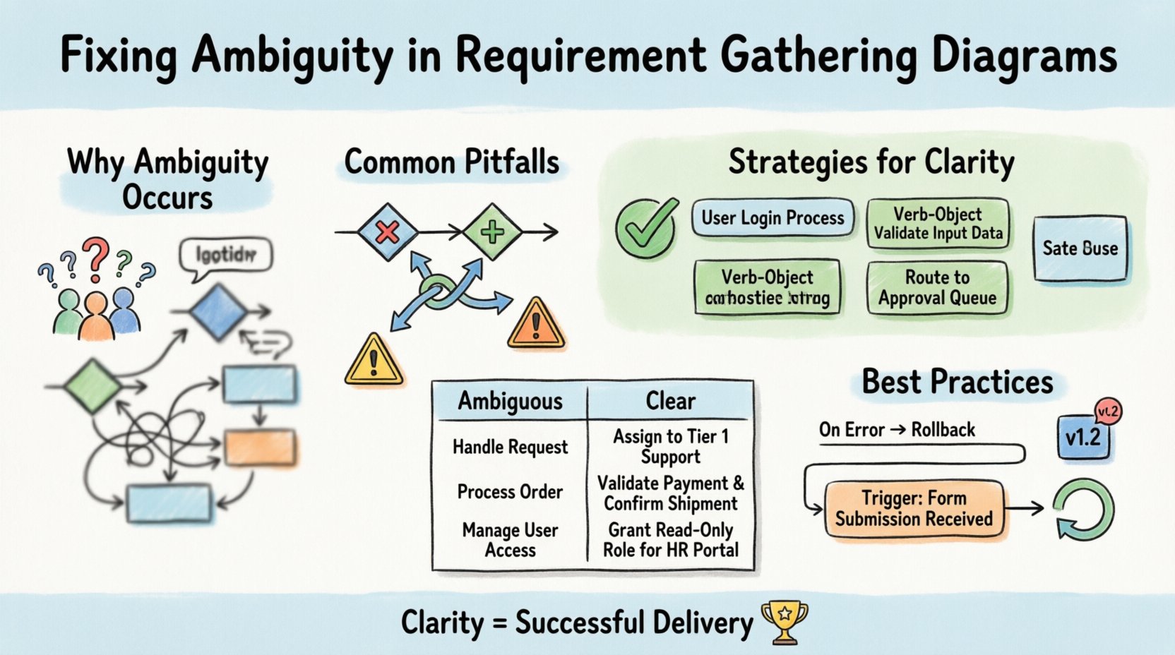
| Task Name | “Handle Request” | “Assign Request to Tier 1 Support” |
| Gateway Condition | “If Valid?” (No text) | “If Valid? Yes/No” |
| Trigger | “Start when ready” | “Start on Submission of Form ID-101” |
| Exception Handling | “If Error, fix later” | “If Error, Route to Audit Queue” |
| Data Input | “User Data” | “Customer ID, Account Type, Balance” |
Notice how the “Clear Approach” leaves no room for guesswork. The developer knows exactly what data to expect, and the stakeholder knows exactly when the process ends.
🔍 Validation Techniques
Once a diagram is drafted, it must undergo validation. This is not just a review; it is a test of understanding. Validation ensures the model reflects reality.
1. Walkthrough Sessions
Conduct a walkthrough with the subject matter experts. Walk through the process step-by-step. Ask them to trace the path from start to finish. If they hesitate, you have found an ambiguity. Do not assume they understand the notation; ask them to explain the logic back to you.
2. Scenario Testing
Run specific scenarios against the diagram. For example, “What happens if the user submits an invalid email?” Trace the path. Does the diagram have a branch for this? If the diagram assumes valid input only, it is incomplete. Test happy paths and unhappy paths equally.
3. Traceability Matrix
Link requirements to diagram elements. If a requirement states “System must send an email,” there must be a Message Flow leading to a Send Event. This ensures nothing is modeled without a source requirement. It also prevents the inclusion of features that were not requested.
🗣️ Stakeholder Communication
A diagram is a communication tool. If the stakeholders cannot read it, it fails. Avoid technical jargon in the labels. Instead of “BPEL Orchestration,” use “Coordinate Approval.” The audience may be non-technical, so the visual language must bridge the gap between business needs and technical implementation.
Regular feedback loops are essential. Do not present a final diagram after months of work. Present drafts early and often. This allows stakeholders to correct misunderstandings before they are baked into the design. Collaboration ensures that the model evolves with the understanding of the business.
🛡️ Governance and Versioning
Processes change. Requirements shift. To maintain clarity, you must manage versions. A diagram from last year may not reflect current rules. Maintain a version history for every process map. This helps teams understand why a specific decision was made at a certain time.
Key governance practices include:
- Change Control: Any change to the diagram requires approval from the process owner.
- Documentation: Keep a separate document explaining complex rules that do not fit in the diagram.
- Training: Ensure all team members know the notation standards. If everyone uses the symbols differently, ambiguity returns.
💡 The Cost of Ignoring Precision
Ignoring ambiguity has tangible costs. When a developer interprets a diagram differently than the analyst, the resulting code must be rewritten. This is known as rework. Rework consumes resources and delays time-to-market. Furthermore, ambiguous requirements often lead to security gaps. If a process step is not clearly defined, security checks might be skipped.
Investing time in fixing ambiguity upfront saves significant effort downstream. It is better to spend an extra hour clarifying a gateway than to spend a week debugging the resulting application.
🔄 Iterative Refinement
Modeling is rarely a one-time event. It is an iterative cycle. Start with a high-level view, then drill down. As you refine the details, you will often find contradictions in the high-level view. This is normal. Use these contradictions to refine the requirements.
Continuous refinement ensures the diagram remains accurate. As the business environment changes, the diagram must adapt. A static diagram becomes obsolete quickly. Treat the diagram as a living document that supports the business, not just a static artifact for compliance.
🎯 Summary of Best Practices
To ensure your requirement gathering diagrams are free of ambiguity, adhere to these core principles:
- Label Every Path: Never leave a gateway branch unlabeled.
- Define Triggers: Be explicit about what starts the process.
- Use Standard Symbols: Stick to the official BPMN specification.
- Validate with Users: Get sign-off from the people doing the work.
- Document Logic Separately: Use text for complex rules, symbols for flow.
- Version Control: Track changes and updates over time.
By following these guidelines, teams can build a foundation of clarity. Precision in modeling leads to precision in execution. When the diagram is unambiguous, the team can focus on solving business problems rather than deciphering the process flow.
Clarity is not just a nice-to-have feature; it is a requirement for successful delivery. Take the time to fix ambiguity now, and the benefits will be felt throughout the project lifecycle.

