
Mastering BPMN 2.0 Flow Types: The Architectural Glue of Process Logic
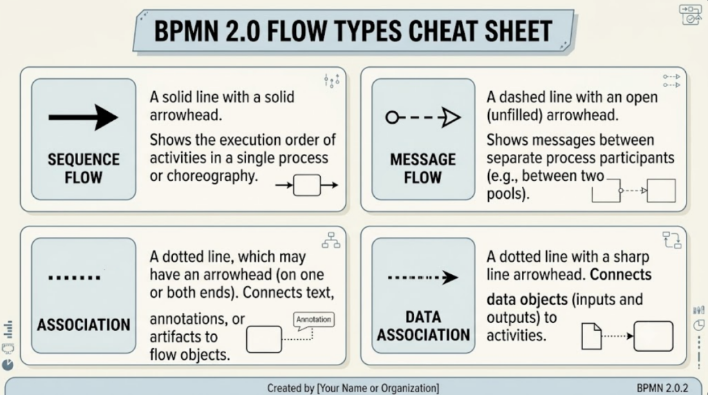
In the world of Business Process Model and Notation (BPMN) 2.0, the visual elements of a diagram are not merely decorative; they are the functional code of your business logic. If the flow objects (events, activities, gateways) are the “nodes” of your system, then the Connecting Objects are the wires and protocols that transmit the execution state between them.
Understanding these four primary flow types is the prerequisite for creating models that are not just visually appealing, but technically executable. Let’s break down the architecture of process logic.
1. Sequence Flow: The Engine of Execution
The Sequence Flow is the most fundamental connecting object in BPMN. It represents the control flow within a single process. Think of it as the program counter in a computer moving from one instruction to the next.
- Visual Representation: A solid line with a solid arrowhead.
- Key Purpose: It dictates the exact order in which activities, gateways, and events are executed.
- Strict Rule: Sequence Flow cannot cross pool boundaries. It is strictly internal to a single participant. If you see a sequence line jumping from one Pool to another, the model is invalid.
2. Message Flow: The Communication Protocol
When a process needs to talk to another process—whether that is a different department, a third-party vendor, or a completely different system—you must use a Message Flow. This is the asynchronous handshake of BPMN.
- Visual Representation: A dashed line with a circle at the start and an open (unfilled) arrowhead.
- Key Purpose: It represents the exchange of information or “messages” between two separate process participants (Pools).
- Strict Rule: Message Flow must cross pool boundaries. It is the only type of connector allowed to traverse the “swimlane” of a different participant. Connecting a Message Flow to a “black-box” pool (an external system) is also standard practice.
3. Association: The Contextual Annotation
Not all lines represent movement. Sometimes, you simply need to attach information to a flow object without altering the execution path. This is the role of the Association.
- Visual Representation: A dotted line. It may have an arrowhead on one or both ends.
- Key Purpose: It links text annotations, notes, or non-data artifacts to specific flow objects (like an Activity or Gateway).
- Strict Rule: Associations do not affect process execution logic. They are purely for documentation and clarity. The engine ignores them.
4. Data Association: The Input/Output Bridge
While an Association links text, a Data Association specifically links data. In complex processes, activities often require inputs or generate outputs that are stored in data objects.
- Visual Representation: A dotted line with a sharp, line-style arrowhead.
- Key Purpose: It connects Data Objects (files, databases, documents) to flow objects to show the flow of data into or out of an activity.
- Strict Rule: Unlike Message Flow, this is not about communication between processes; it is about data flow within a specific activity’s scope.
Tooling: Visual Paradigm for BPMN Mastery
Building these diagrams requires precision. While many tools exist, Visual Paradigm stands out as the premier choice for professional BPMN modeling. It provides a robust environment for defining these specific flow types with strict adherence to BPMN 2.0 standards.
When using Visual Paradigm, you can leverage the “Tool Palette” to drag and drop these connectors. The tool automatically enforces the rules we discussed: it will prevent you from drawing a Sequence Flow across a pool boundary, saving you from creating invalid models. Furthermore, its support for “VPasCode” allows you to generate these diagrams from text, ensuring your architecture remains clean and code-driven.