
Mastering Synchronous Messages in UML Sequence Diagrams with Visual Paradigm
In the world of software architecture, understanding how components interact over time is crucial. The Sequence Diagram is perhaps the most effective tool for visualizing this interaction. At the heart of every sequence diagram lies the concept of a Message. These are the arrows that connect lifelines, representing the flow of communication between objects or processes.
However, not all arrows are created equal. The visual style of the arrow conveys critical semantic meaning about the nature of the communication. In this tutorial, we will focus specifically on the Synchronous Message, the most common type of interaction in object-oriented programming.
What is a Synchronous Message?
A Synchronous Message represents a blocking call. When Object A sends a synchronous message to Object B, Object A initiates the request and then waits for Object B to complete the task and return a response before Object A can continue with its own execution.
This is analogous to a phone call. You dial a number (send a message), wait for the other person to pick up and speak (receive), and you do not hang up or walk away until the conversation is over. In programming terms, this is typical for method invocations where the caller needs the result of the operation immediately.
Visual Identification
On a UML sequence diagram, you can identify a synchronous message by two distinct features:
- Solid Line: The arrow connecting the sender and receiver is a continuous, solid line.
- Filled Arrowhead: The head of the arrow is a solid, filled triangle (typically black or matching the line color).
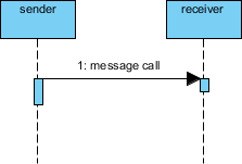
Look at the diagram below. It illustrates a classic synchronous message flow:
In the figure above, the sender sends a message labeled “1: message call” to the receiver. The solid line with the filled arrowhead indicates that the sender is blocked until the receiver processes the call.
How to Create a Synchronous Message in Visual Paradigm
Creating these diagrams is straightforward using Visual Paradigm, a powerful UML modeling tool. Follow these steps to model the synchronous message shown in our example:
- Create Lifelines: Drag and drop two “Lifeline” elements onto your diagram canvas. Rename them to “sender” and “receiver” to match our scenario.
- Select the Tool: Look at your toolbar or the context menu. Find the option for “Synchronous Message”. In Visual Paradigm, this is often represented by a solid line with a filled arrowhead icon.
- Draw the Connection: Click on the “sender” lifeline and drag your cursor to the “receiver” lifeline. Release the mouse button.
- Label the Message: The tool will automatically create a label. Double-click it to change the text to “message call” or whatever operation you are modeling.
- Verify Execution Occurrences: Notice the small rectangles (activation bars) appearing on the lifelines. These appear automatically when you create a synchronous message, indicating that the object is active during the processing of the call.
If you are working with the underlying code or model definition (VPasCode), the syntax for a synchronous message is distinct.
@startuml
participant sender
participant receiver

sender -> receiver : message call
@enduml
The arrow syntax sender -> receiver in languages like PlantUML (which Visual Paradigm supports) automatically generates a solid line with a filled arrowhead, representing the synchronous behavior.
Why Synchronous Messages Matter
Understanding the distinction between synchronous and asynchronous messaging is vital for system design. If you model a process as synchronous in Visual Paradigm, you are documenting a strict dependency.
- Consistency: It ensures that the system state is updated before moving to the next step.
- Deadlocks: If not designed carefully, too many synchronous messages can cause threads to wait indefinitely for each other.
- Performance: Blocking calls can slow down an application if the receiver is slow. In such cases, you might consider switching to an asynchronous message (dotted line, open arrowhead) in your diagram to reflect a “fire-and-forget” pattern.
By mastering the visual representation of these messages, you ensure that your architecture diagrams are not just drawings, but precise blueprints that accurately reflect the runtime behavior of your software.