
Mastering UML: Visual Paradigm Sequence Diagrams & Control Flow
Visual Paradigm is one of the most powerful tools available for software engineers and system architects, particularly when it comes to defining the behavior of a system over time. While static diagrams like Class Diagrams show structure, Sequence Diagrams bring that structure to life by visualizing the interaction between objects.
This tutorial will guide you through the essential components of a Sequence Diagram, specifically focusing on Combined Fragments and Control Flow. We will dissect a complex interaction scenario involving loops and conditional breaks, showing you how to model real-world logic using Visual Paradigm.
1. The Foundation: Lifelines and Activation Bars
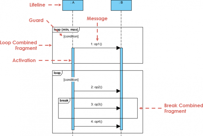
Every Sequence Diagram begins with participants, known as Lifelines. These are represented by vertical rectangles at the top of the diagram (e.g., :A and :B in our example). A dashed line extends downward from this rectangle, representing the timeline of the participant.
As messages are exchanged, the participant becomes “active.” This period of activity is visualized by a thin, vertical blue rectangle on the lifeline, known as an Activation Bar.
- Lifeline: The vertical dashed line representing an object’s existence over time.
- Activation: The rectangular bar indicating when an object is performing an action or waiting for a response.
2. The Message Flow
The core of a sequence diagram is the Message. These are arrows connecting the activation bars of different lifelines. They represent method calls, data transfers, or signals.
In our diagram, we see a sequence of calls:
1: op1() – The initial trigger.2: op2() – A call occurring within a specific context.3: op3() – A conditional operation.4: op4() – The final operation.
Visual Paradigm allows you to define these messages as synchronous (solid arrow) or asynchronous (dashed arrow), and you can assign unique IDs to them for easy reference.
3. Advanced Logic: Combined Fragments
Real-world software rarely follows a straight line. It involves loops, conditions, and breaks. Visual Paradigm handles this complexity using Combined Fragments. These are the large rectangular frames that encapsulate a group of messages.
The Loop Fragment
At the top of our diagram, we see a frame labeled loop. This is the standard UML pattern for repeating an interaction.
- Guard Condition: Notice the text
[condition]inside the loop frame. This is the guard. The loop will only execute if this condition evaluates to true. - Iteration Limits: The label
loop (min, max)allows you to define strict constraints on how many times the loop runs.
The Break Fragment
Inside the main loop, we encounter a nested fragment labeled break. This is a critical modeling concept. It defines an area where the execution of the enclosing loop is terminated immediately.
When the system executes the op3() message, the break fragment is triggered. This signals to the Visual Paradigm engine that the outer loop should stop iterating, regardless of whether the guard condition is still met.
4. Modeling Syntax and Best Practices
When using Visual Paradigm, you can model these fragments using the visual canvas or by using the text-based VPasCode editor. Understanding the syntax helps in debugging and ensuring compatibility.
Here is how the logic in our diagram translates into standard UML syntax:
participant A
participant B

== Loop Interaction ==
loop [condition]
    A -> B : 1: op1()

    == Break Interaction ==
    break [condition]
        A -> B : 3: op3()
    end

    A -> B : 2: op2()
    A -> B : 4: op4()
end
Notice how the break block is nested inside the loop block. This nesting is what creates the hierarchy of control flow. If op3() is called, the diagram interprets this as a signal to exit the loop scope entirely.
Why Use Combined Fragments?
Without combined fragments, you would have to draw multiple separate diagrams to show the “normal” path and the “exception” path. Combined fragments allow you to maintain a single view of the logic, reducing complexity and preventing diagram fragmentation.
Conclusion
By mastering the use of lifelines, activation bars, and specifically Combined Fragments like loop and break, you can create Sequence Diagrams that are not just pretty pictures, but accurate blueprints of your system’s logic. Visual Paradigm provides the flexibility to model these complex interactions visually, ensuring your design is robust and your documentation is clear.