


Designing robust software systems requires more than just functional logic; it demands a foundation built on security. When architects visualize infrastructure, they utilize UML Deployment Diagrams to map out hardware, software, and communication paths. However, a standard diagram often overlooks the critical security layers necessary for protection. Integrating security considerations directly into the deployment model ensures that vulnerabilities are identified during the design phase rather than during production.
This guide explores how to embed security controls, trust boundaries, and compliance requirements into UML deployment modeling. By treating security as a first-class citizen in architectural diagrams, teams can construct systems that are resilient against threats from the outset.
🏗️ Understanding the Deployment Landscape
A UML Deployment Diagram represents the physical architecture of a system. It depicts artifacts, nodes, and the connections between them. Without security annotations, this view remains purely structural. To make it secure, one must understand the components:
- Nodes: These represent physical or virtual computing resources. They could be servers, routers, or cloud instances.
- Artifacts: These are physical pieces of information, such as executable code, data files, or libraries.
- Communication Paths: The network links that allow nodes to exchange data.
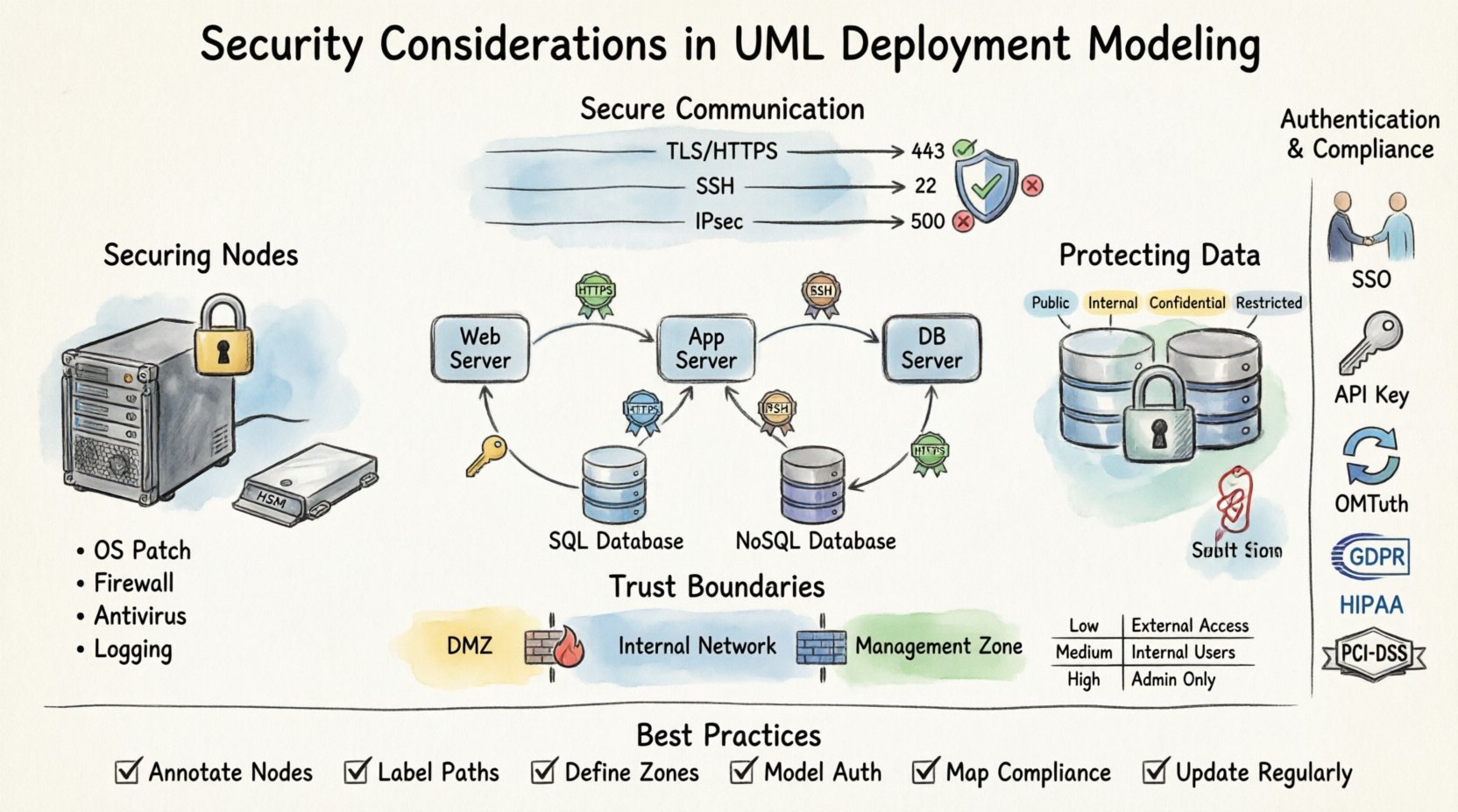
When modeling these elements, security context must be applied to every node. A generic server node is insufficient. The model should distinguish between a public-facing web server and an internal database server. The distinction lies in the security posture required for each.
🔒 Securing Nodes and Hardware
Nodes are the physical or virtual endpoints where software executes. In a security-focused model, every node requires specific attributes regarding its hardening and access controls.
Physical and Logical Nodes
Deployment models often conflate physical hardware with logical instances. Security modeling must separate these:
- Physical Nodes: These represent actual hardware like servers or IoT devices. Security considerations include physical access controls, tamper-proofing, and environmental controls.
- Logical Nodes: These represent virtual machines, containers, or cloud functions. Security considerations here focus on isolation, hypervisor security, and runtime environments.
Hardware Security Modules (HSM)
Critical systems often rely on specialized hardware for cryptographic operations. In the diagram, these should be explicitly modeled as dedicated nodes. This highlights that key management is not happening in software memory but in a secure hardware boundary.
Server Hardening Status
Each server node should carry metadata regarding its security configuration. This includes:
- Operating System version and patch level.
- Firewall rules active on the node.
- Antivirus or endpoint protection status.
- Logging capabilities enabled for audit trails.
By annotating these details, architects can ensure no node is left unpatched or unmonitored in the final infrastructure.
💾 Protecting Artifacts and Data Stores
Artifacts are the files and components deployed to nodes. Not all artifacts carry the same risk profile. Some contain sensitive data, while others are public libraries. Security modeling requires differentiating these based on sensitivity and integrity requirements.
Data Classification
Data stores within the deployment model must be labeled according to classification levels. Common categories include:
- Public: No security controls beyond availability.
- Internal: Accessible only within the organization network.
- Confidential: Requires encryption and strict access controls.
- Restricted: Highly sensitive data subject to regulatory compliance.
Encryption at Rest
When modeling data stores, the diagram should indicate whether data is encrypted while stored. This is crucial for compliance and data protection. If a node holds restricted data, the artifact storage should be annotated with an encryption symbol or note.
Consider the following scenarios:
- Database Server: Should indicate full disk encryption or column-level encryption for sensitive fields.
- File Server: May require encryption for specific document types.
- Cache Server: Often holds session tokens; requires strict memory isolation.
Artifact Integrity
Ensuring that the code deployed has not been tampered with is vital. Deployment models should reflect mechanisms for artifact verification, such as digital signatures or checksums. This ensures that only trusted software runs on the nodes.
🔗 Securing Communication Paths
The connections between nodes are often the weakest link in a system. Data traversing these paths is susceptible to interception, modification, or denial of service. The deployment diagram must explicitly define the security protocols used for communication.
Protocol Specification
Generic lines between nodes are ambiguous. Each link should specify the protocol and security layer:
- HTTPS/TLS: Required for web traffic and API calls.
- SSH: For secure remote administration.
- IPSec: For site-to-site tunneling.
- Unencrypted TCP: Should be avoided and highlighted as a risk if unavoidable.
Port Management
Ports open on a node define its attack surface. In the diagram, administrators should document which ports are exposed to external networks versus internal networks. This helps in identifying unnecessary exposure.
Key considerations include:
- Ingress Ports: Where does traffic enter the node?
- Egress Ports: Where does traffic leave the node?
- Management Ports: Ports used for administration should never be exposed to the public internet.
Bandwidth and Rate Limiting
Security also involves availability. Denial of Service attacks target communication paths. The model should consider rate limiting policies. While not always drawn as a diagram element, the architecture should account for load balancers or firewalls that mitigate traffic floods.
🛡️ Defining Trust Boundaries and Zones
Trust boundaries are critical in deployment modeling. They define where trust ends and verification begins. Crossing a trust boundary requires authentication and authorization. Visualizing these zones helps stakeholders understand where security checks occur.
Network Segmentation
Nodes should be grouped into logical security zones:
- DMZ (Demilitarized Zone): Public-facing services isolated from internal resources.
- Internal Network: Trusted infrastructure for core business logic.
- Management Network: Dedicated network for administrative tasks, separated from user traffic.
- Quarantine Zone: For systems that require isolation due to security risks.
Trust Levels
Each zone represents a different level of trust. Data moving from a low-trust zone to a high-trust zone must undergo scrutiny. The deployment diagram should show the flow of data across these boundaries and the security gates involved.
Firewall Rules
Firewalls are the enforcement points for these zones. In the model, firewalls should be represented as nodes or gateways between zones. Rules should be summarized to show what traffic is allowed to pass.
| Zone | Trust Level | Access Control | Encryption Required |
|---|---|---|---|
| Public Internet | Untrusted | Whitelist Only | Yes (TLS 1.2+) |
| DMZ | Low | Restricted Ingress | Yes |
| Internal Network | Medium | Role-Based | Optional (Internal) |
| Management Zone | High | MFA Required | Yes (Strong) |
🆔 Modeling Authentication and Authorization
Security is not just about the hardware; it is about who and what can access the resources. Authentication (who you are) and Authorization (what you can do) must be modeled alongside the infrastructure.
Identity Providers
Centralized identity management should be depicted. If the system uses a specific identity provider for authentication, this node should be linked to all dependent services. This highlights the dependency and potential single point of failure.
Authentication Mechanisms
Each node or service should indicate the authentication method it supports:
- Single Sign-On (SSO): For user-facing applications.
- API Keys: For service-to-service communication.
- Certificates: For machine-to-machine communication.
- OAuth/OIDC: For delegated authorization.
Authorization Policies
Authorization logic should be documented in the deployment model notes. For example, a database node might allow read access from the application server but deny write access. These permissions define the data flow security.
⚖️ Compliance and Regulatory Mapping
Many industries operate under strict regulatory frameworks. Deployment diagrams must reflect these requirements to ensure legal compliance. Failing to model compliance can lead to architectural debt and legal penalties.
Key Regulations
Depending on the industry, specific standards apply:
- GDPR: Requires data protection and right to erasure capabilities within the infrastructure.
- HIPAA: Mandates strict controls on health data access and storage.
- PCI-DSS: Governs how payment card data is handled and stored.
- SOC 2: Focuses on security, availability, and processing integrity.
Data Residency
Some regulations require data to remain within specific geographic boundaries. The deployment model should indicate the physical location of nodes. This ensures that data does not cross borders in violation of local laws.
Audit Trails
Compliance often requires logging. The diagram should show where logs are generated and where they are stored. Log storage nodes must be separate from operational nodes to prevent log tampering.
🐛 Vulnerability Identification in Diagrams
A well-structured deployment diagram can serve as a tool for vulnerability identification. By visualizing the system, architects can spot weaknesses before code is written.
Single Points of Failure
If a critical node has no backup or redundancy, it represents a risk. The diagram should highlight high-availability configurations. Clustering and load balancing should be visible to show resilience.
Exposed Management Interfaces
Management interfaces (like SSH or RDP) are common entry points for attackers. If these are exposed to the internet in the diagram, it is a red flag. They should be routed through a bastion host or jump box.
Unencrypted Channels
Any line in the diagram without encryption notation is a potential risk. Security reviews should focus on these lines and mandate encryption upgrades.
🧠 Integrating Threat Modeling
Deployment modeling is a precursor to formal threat modeling. Once the infrastructure is mapped, teams can apply methodologies like STRIDE to identify threats specific to the architecture.
Threat Categories
Map the following threats to the diagram elements:
- Spoofing: Can an attacker impersonate a node or user?
- Tampering: Can data in transit or at rest be modified?
- Repudiation: Can users deny actions taken?
- Information Disclosure: Is sensitive data exposed in logs or memory?
- Denial of Service: Can the system be overwhelmed?
- Elevation of Privilege: Can a user gain higher access than granted?
Data Flow Analysis
Trace the data flow across the diagram. Where does sensitive data originate? Where does it terminate? At which points is it transformed? Each transformation point is a potential vulnerability.
🔄 Maintaining Security Integrity
A deployment diagram is not a static document. Infrastructure changes, patches are applied, and new services are added. The model must evolve to maintain security integrity.
Version Control
Deployment models should be versioned alongside the codebase. This allows teams to compare architecture changes over time and audit security updates.
Automated Validation
Modern tooling can validate the diagram against security policies. If a new node is added without encryption, the tool should flag it. This ensures that the model remains accurate and secure.
Regular Audits
Periodic reviews of the deployment model are necessary. Security teams should verify that the physical infrastructure matches the logical model. Drift between the two creates security gaps.
📝 Summary of Best Practices
Integrating security into UML deployment modeling is a strategic imperative. It shifts security from a reactive check to a proactive design element. By following these guidelines, teams can build architectures that are secure by design.
Key takeaways for implementation include:
- Annotate Nodes: Define security status for every server and device.
- Label Paths: Specify protocols and encryption on all connections.
- Define Zones: Clearly mark trust boundaries and segmentation.
- Model Auth: Show how identity and access are managed.
- Map Compliance: Ensure regulatory requirements are visible.
- Update Regularly: Keep the diagram synchronized with the environment.
Security is a continuous process. The deployment diagram is the map for that journey. A clear, accurate, and security-focused map ensures the journey remains safe from start to finish.

