


Business processes are rarely linear. They involve branching paths, conditional logic, and critical choices that determine the outcome of an operation. When these processes become intricate, clarity is often lost. Stakeholders struggle to understand the flow, developers face ambiguity during implementation, and auditors find gaps in compliance logic. This is where the Business Process Model and Notation (BPMN) framework provides essential structure. By utilizing specific symbols, organizations can map out logic without ambiguity. This guide explores how BPMN symbols simplify complex decisions and ensure operational consistency.
Understanding the Visual Language of Flow 🗺️
Before diving into decision points, it is necessary to understand the foundational elements that make up a process diagram. BPMN is designed to be a standard that bridges the gap between business analysts and technical teams. It relies on a set of graphical symbols to represent the lifecycle of a task. Without these standardized symbols, diagrams become personal sketches rather than executable specifications.
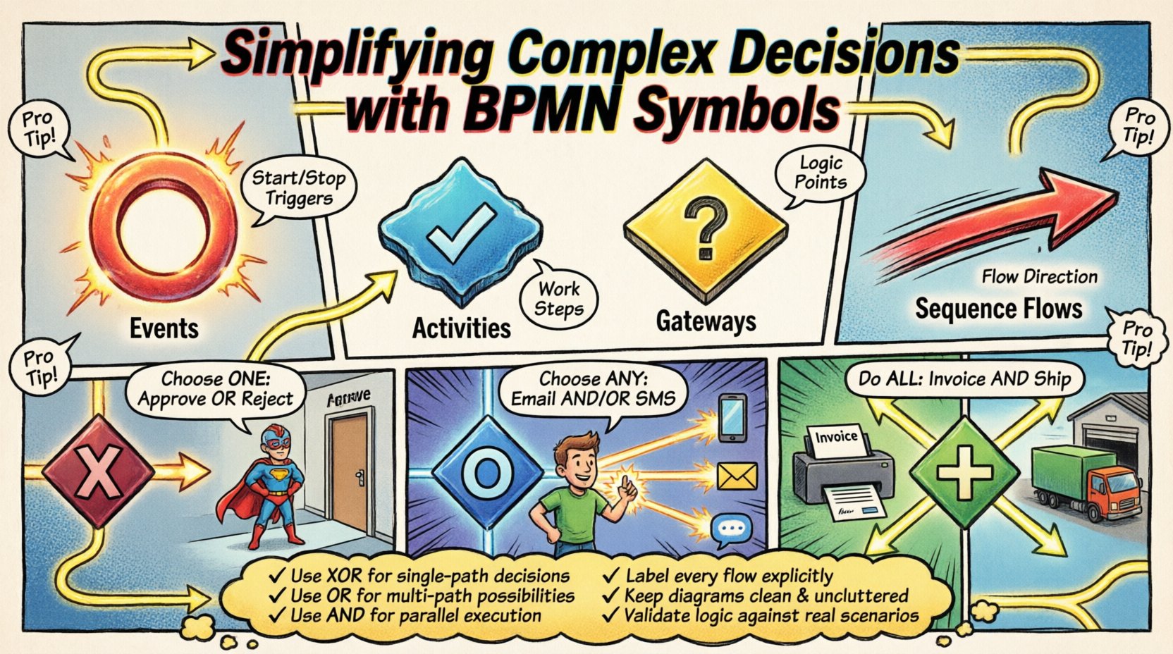
- Events: These are the triggers and results of a process. They are depicted as circles. An event starts the journey, stops it, or signals a change during execution.
- Activities: Represented by rounded rectangles, these are the work being done. They range from a single step to a complex sub-process.
- Gateways: The diamonds in the diagram. These are the decision points where the path diverges or converges.
- Sequence Flows: The arrows connecting the shapes. They define the order of execution.
When complexity increases, the volume of activities grows. However, the real challenge lies in the logic that dictates which activity happens next. This is the domain of gateways. A well-modeled gateway ensures that the process adapts to data conditions rather than forcing a rigid path.
The Mechanics of Decision Making ⚙️
Decisions in business processes are rarely simple yes-or-no scenarios. They often depend on multiple variables, data thresholds, or external approvals. Using the correct BPMN symbol for these scenarios prevents logical errors and reduces the risk of process failure. The core symbol for decision-making is the Gateway. While it looks like a simple diamond, the internal logic varies significantly based on the type used.
Improper use of gateways can lead to deadlocks, where the process waits indefinitely for a condition that will never be met. Conversely, using the wrong gateway type can cause the process to skip necessary steps. For example, a process might require both an approval and a data validation check before proceeding. If modeled incorrectly, the system might proceed with only one of these checks, creating a compliance risk.
To simplify these scenarios, modelers must understand the distinct behavior of each gateway type. The goal is to represent the business rule accurately so that the execution engine interprets it correctly. This reduces the need for custom code to handle exceptions later in the development phase.
Gateway Types Explained 🚦
There are three primary gateway types used for logic control. Each serves a specific purpose in managing the flow of tokens through the process. Understanding the difference is critical for accurate modeling.
- Exclusive Gateway (XOR): This is the most common decision point. It requires that only one path is taken. If condition A is true, path A is executed. If condition B is true, path B is executed. Only one can be active at a time.
- Inclusive Gateway (OR): This allows for multiple paths to be taken simultaneously. It is used when more than one condition can be true at once. For example, a notification might be sent via email and SMS if specific thresholds are met.
- Parallel Gateway (AND): This splits the flow into multiple paths that run concurrently. It also merges paths that must all complete before the process continues. It does not evaluate conditions; it simply duplicates the flow.
Using these symbols effectively requires a clear understanding of the business requirements. If a requirement states that either approval is needed, an XOR gateway is appropriate. If both approvals are needed, an AND gateway is required. If any of three risk factors are triggered, an OR gateway handles the branching.
Comparison of Gateway Logic
| Gateway Type | Logic Behavior | Typical Use Case |
|---|---|---|
| Exclusive (XOR) | Selects exactly one outgoing path. | Approve or Reject loan application. |
| Inclusive (OR) | Selects one or more outgoing paths. | Notify sales team and update CRM. |
| Parallel (AND) | Splits into all paths; waits for all to complete. | Generate invoice and ship goods. |
The table above highlights the distinct behaviors. Confusing an Exclusive gateway with an Inclusive one is a common error. If a modeler uses an XOR gateway for a task that requires parallel processing, the system will stop after the first parallel task completes, leaving the others pending. This leads to incomplete transactions and data inconsistency.
Designing for Clarity and Maintenance 🛠️
Even with the correct symbols, a diagram can become unreadable if not designed with maintenance in mind. Complex decisions often lead to spaghetti-like diagrams where lines cross over each other, making it difficult to trace the flow. To avoid this, follow specific design principles that prioritize readability.
- Keep Conditions Simple: Avoid writing complex logical statements directly on the sequence flow. Instead, use decision tables or external data objects to define the rules. This keeps the diagram clean.
- Use Sub-Processes: If a decision logic is deep, encapsulate it within a sub-process. This hides the complexity until a specific level of detail is required.
- Consistent Labeling: Ensure that every sequence flow leaving a gateway is labeled with a clear condition. Never leave a flow unlabeled unless it represents a default path.
- Visual Hierarchy: Use swimlanes to group activities by role or system. This helps stakeholders see who is responsible for each decision node.
Maintaining a diagram is an ongoing task. As business rules change, the model must be updated. A well-structured model makes these updates easier. If the symbols are used correctly, a change in logic might only require modifying a condition label rather than restructuring the entire path.
Common Modeling Mistakes ❌
Experienced modelers often encounter specific pitfalls when dealing with complex decisions. Recognizing these mistakes early can save significant time during the review phase.
- Unreachable Paths: Creating a branch that can never be triggered. This often happens when conditions are mutually exclusive or impossible to satisfy based on data constraints.
- Missing Exit Conditions: A gateway with multiple outgoing paths but no default path for the “else” case. If no condition is met, the process halts.
- Overuse of Gateways: Using a gateway for every minor variation. This fragments the process and makes the high-level view hard to understand. Use gateways only where the flow fundamentally changes.
- Confusing Start and End Events: Placing a gateway where an event should be. Gateways are for control flow, not for starting or stopping the process.
Addressing these issues requires a review process. Peer reviews are essential to identify paths that logic dictates should not exist. Automated validation tools can also help detect deadlocks or unreachable nodes before the model is deployed.
Integration with Business Logic 💡
Finally, the symbols in a diagram must align with the actual logic running in the system. A diagram is a contract between the business and the technology team. If the symbols suggest one behavior but the code implements another, the process will fail.
For instance, an XOR gateway in the model implies that the execution engine will evaluate conditions sequentially until one is met. In some systems, this evaluation order matters. If the business rule does not specify priority, the model should reflect a random selection or a specific order to avoid ambiguity.
Furthermore, complex decisions often involve external systems. A decision might depend on the response from a third-party API. In this case, the gateway should be preceded by an intermediate event or an activity that fetches the data. This ensures the decision is made on current information rather than stale data.
Summary of Best Practices 📝
Adopting a disciplined approach to BPMN modeling pays dividends in operational efficiency. By adhering to the standard symbols and logic, teams reduce the cognitive load required to understand the process.
- Use XOR for single-path decisions.
- Use OR for multi-path possibilities.
- Use AND for parallel execution.
- Label every flow explicitly.
- Keep the diagram clean and uncluttered.
- Validate logic against real-world scenarios.
When these practices are applied, the resulting diagrams serve as reliable documentation. They become living documents that guide development, support auditing, and facilitate training. The symbols act as a universal language, ensuring that everyone from the CEO to the developer understands the intended workflow.
Complexity is inevitable in business. However, the representation of that complexity does not have to be confusing. With the right symbols and a structured approach, even the most intricate processes can be simplified and understood clearly.

