


Introduction
In today’s rapidly evolving software development landscape, the ability to quickly and accurately design database structures has become more critical than ever. Organizations face increasing pressure to deliver robust, scalable systems while maintaining efficiency and reducing time-to-market. Traditional database design methods, while reliable, often require significant time investment and specialized expertise that can create bottlenecks in development workflows.
The emergence of AI-powered tools has begun to revolutionize how teams approach database modeling and documentation. This case study examines the integration of Entity Relationship Diagram (ERD) support within Visual Paradigm’s OpenDocs platform, with a particular focus on its innovative AI ERD generation capabilities. By exploring how this technology bridges the gap between natural language descriptions and structured database designs, we demonstrate how modern teams can accelerate their development cycles while maintaining high standards of data modeling excellence.
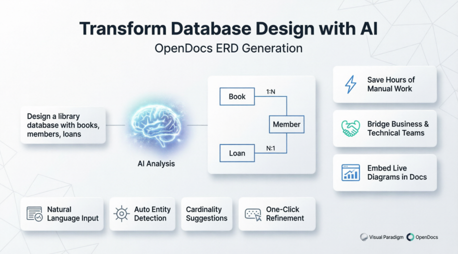
Through this comprehensive analysis, we will explore the fundamental concepts of ERDs, examine practical implementation strategies, and evaluate the tangible benefits that AI-powered diagram generation brings to database design workflows across various organizational contexts.
Case Study Background
Visual Paradigm, a leader in visual modeling and documentation tools, recognized a significant opportunity to enhance their OpenDocs platform by integrating comprehensive Entity Relationship Diagram support. OpenDocs, positioned as an AI-powered knowledge management tool, serves diverse professionals including software engineers, database architects, business analysts, and project managers who require efficient ways to document, visualize, and collaborate on system designs.
The challenge was clear: traditional ERD creation methods are time-consuming and error-prone, often requiring hours of manual work to translate conceptual requirements into structured database models. This process typically demands deep technical expertise in database design principles, familiarity with specific notation standards, and meticulous attention to detail when defining entities, attributes, and relationships.
The Challenge: Traditional Database Design Bottlenecks
Organizations implementing database-driven applications frequently encounter several critical challenges:
Time-Intensive Manual Processes: Database designers and developers spend considerable time translating business requirements into entity relationship diagrams. This manual process involves identifying entities, defining attributes, establishing relationships, and ensuring proper cardinality—all while maintaining consistency across the entire model.
Communication Gaps: Business stakeholders often struggle to articulate their data requirements in technical terms, while technical teams may find it difficult to validate their understanding of business needs without visual representations. This disconnect can lead to costly redesigns and implementation delays.
Documentation Fragmentation: ERDs created in isolation from project documentation create knowledge silos. Teams must switch between multiple tools to access diagrams, requirements, and technical specifications, reducing productivity and increasing the risk of inconsistencies.
Skill Barriers: Creating professional-quality ERDs requires specialized knowledge of database design principles, normalization techniques, and notation standards. This expertise gap can limit an organization’s ability to rapidly prototype and iterate on database designs.
The Solution: AI-Powered ERD Generation in OpenDocs
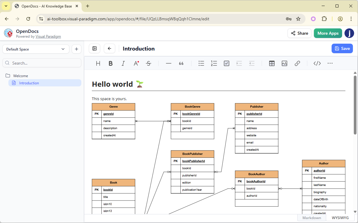
Visual Paradigm’s response to these challenges represents a significant advancement in database design methodology. By embedding full Entity Relationship Diagram support directly into OpenDocs and introducing AI-powered ERD generation, they created a unified platform that transforms how teams approach database modeling.
Core Capabilities
The enhanced OpenDocs platform offers four primary capabilities that address the challenges identified above:
Seamless Diagram Embedding: Users can insert live, editable ERDs directly into any document page, ensuring that database designs remain contextualized within broader project documentation. This integration eliminates the need to switch between tools and maintains a single source of truth for project knowledge.
Dedicated Component Pages: For complex database designs requiring focused attention, teams can create entire pages dedicated to standalone ERDs. This flexibility supports both high-level overviews and detailed schema documentation within the same knowledge base.
Manual Drawing Tools: The platform includes a full-featured diagram editor with drag-and-drop functionality, comprehensive shape libraries, connectors with cardinality notations, and attribute definition tools. This gives experienced database designers precise control over every aspect of their models.
AI-Powered Generation: The revolutionary feature that sets this solution apart is the ability to generate complete ERDs from simple text descriptions. By interpreting natural language problem statements, the AI suggests entities, attributes, relationships, and keys—dramatically reducing the time required to produce initial database models.
Implementation Process: From Concept to Diagram
The implementation of AI-powered ERD generation follows an intuitive workflow designed to minimize the learning curve while maximizing productivity gains.
Step-by-Step Creation Process
Step 1: Accessing the Diagram Editor
Users begin by clicking the Insert button in the top bar of the document editor, which opens the insertion dialog.

Step 2: Selecting ERD Type
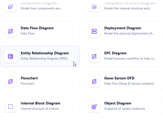
Within the Insert dialog, users navigate to the Diagrams tab and select Entity Relationship Diagram from the available options.
Step 3: Choosing Creation Method
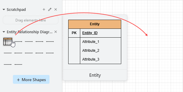
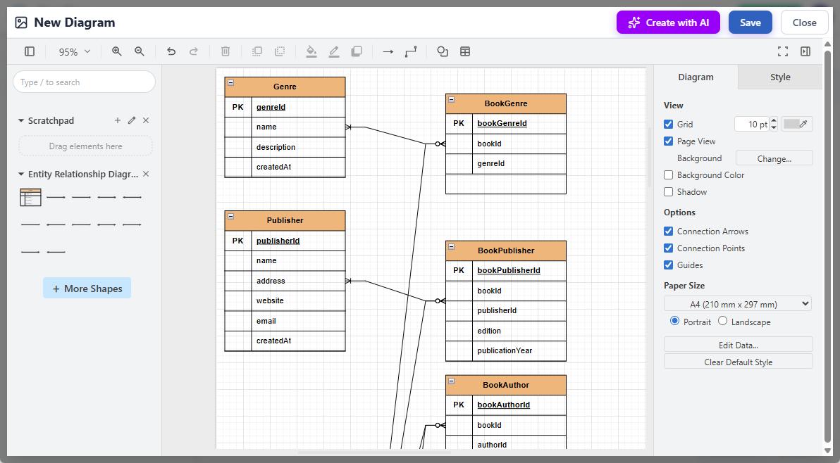
The diagram editor opens with a palette of ERD symbols available for manual creation. Users can drag and drop entities, relationships, and attributes onto the canvas to build diagrams traditionally.
Alternatively, to leverage AI capabilities, users click Create with AI at the top right of the editor.

Step 4: Describing Requirements
Users enter their problem description in natural language. For example: “Design a library database with books, members, loans, and reservations” or “Create an online bookstore system with customers, orders, products, and inventory management.”

Step 5: AI Generation
The AI analyzes the problem description and automatically generates a complete entity relationship diagram with appropriate entities, attributes, relationships, and cardinality notations.
Step 6: Refinement
Users can touch up the generated ERD by adjusting the layout, adding new shapes, modifying attributes, or refining relationships. This hybrid approach combines AI efficiency with human expertise.
Step 7: Saving and Integration
After clicking Save and Close, the diagram is embedded directly into the document, maintaining full editability for future updates.
Understanding ERD Fundamentals
To fully appreciate the value of AI-powered ERD generation, it’s essential to understand the foundational concepts that these diagrams represent.
What is an Entity Relationship Diagram?
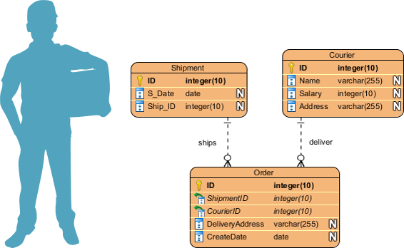
An Entity Relationship Diagram (ERD), also known as an ER Diagram or ER model, is a structural diagram used in database design that visualizes two critical pieces of information: the major entities within the system scope and the inter-relationships among these entities.

Entities typically represent business objects such as people or roles (e.g., Student), tangible objects (e.g., Product), intangible objects (e.g., Log), or events (e.g., Transaction). Relationships define how these entities interact and associate with each other within the system context.
Core ERD Components
Entities
An entity represents a definable thing or concept within a system. In ERD notation, entities appear as rounded rectangles with the entity name displayed at the top and attributes listed in the body.

Attributes
Attributes, also known as columns, are properties or characteristics of an entity. Each attribute has a name describing the property and a type defining the kind of data it holds (e.g., varchar for strings, int for integers).

Primary Keys
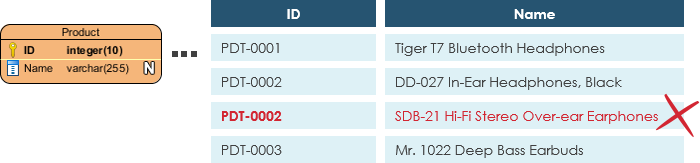
A primary key (PK) is a special attribute that uniquely identifies each record in a database table. No two records can share the same primary key value.
Foreign Keys
A foreign key (FK) references a primary key in another table, establishing relationships between entities. Unlike primary keys, foreign keys need not be unique—multiple records can share the same foreign key values.

Relationships and Cardinality
Relationships indicate how entities associate with each other. Cardinality defines the possible number of occurrences in one entity associated with occurrences in another entity.
One-to-One Relationships: Used primarily to split an entity into two for clarity and organization.

One-to-Many Relationships: An instance of entity X links to many instances of entity Y, but each instance of Y links to only one instance of X.

Many-to-Many Relationships: Instances of entity X link to many instances of entity Y and vice versa. In physical ERDs, these are typically split into pairs of one-to-many relationships.

Data Modeling Abstraction Levels
ER models are typically developed at three levels of abstraction, each serving different purposes and audiences:
Conceptual Data Model
The conceptual ERD models business objects that should exist in a system and their relationships. It provides an overall picture by recognizing business entities without specifying technical implementation details. Notably, conceptual ERDs support generalization (e.g., “Triangle is a kind of Shape”).

Logical Data Model
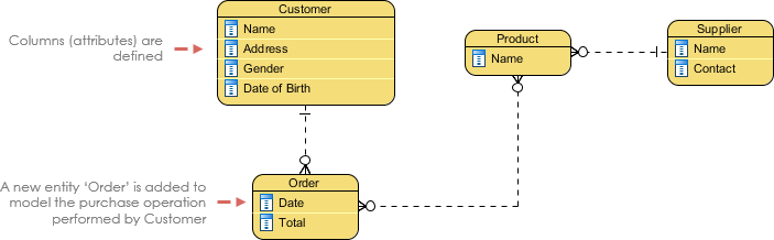
The logical ERD is a detailed version of the conceptual model, explicitly defining columns in each entity and introducing operational and transactional entities. While still independent of specific database systems, it provides sufficient detail for database designers to understand the complete data structure.
Physical Data Model
The physical ERD represents the actual design blueprint of a relational database, assigning specific types, lengths, nullable constraints, primary keys, and foreign keys to each column. This model must consider the conventions and restrictions of the target database management system.
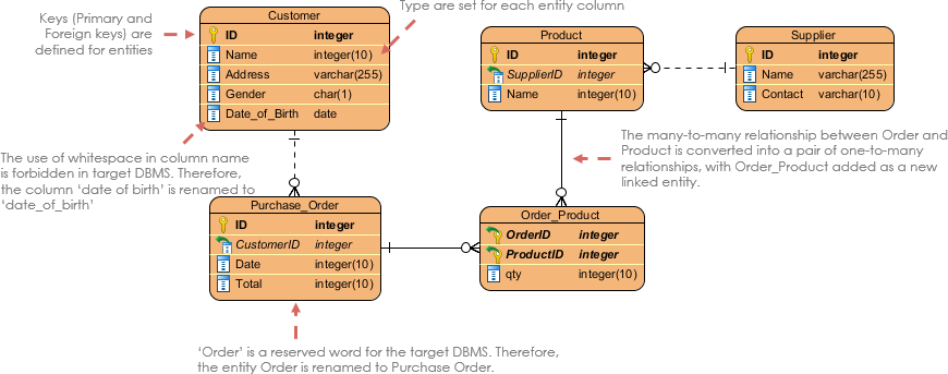
Comparison of Data Model Features:
| ERD Features | Conceptual | Logical | Physical |
|---|---|---|---|
| Entity (Name) | Yes | Yes | Yes |
| Relationship | Yes | Yes | Yes |
| Columns | No | Yes | Yes |
| Column’s Types | No | Optional | Yes |
| Primary Key | No | No | Yes |
| Foreign Key | No | No | Yes |
Practical Applications and Use Cases
The integration of ERD support in OpenDocs addresses multiple real-world scenarios across the software development lifecycle.
Database Design and Planning
When modifying database structures, especially in production environments, direct alterations carry significant risk. ERDs enable teams to visualize and validate design changes before implementation, identifying potential issues and design flaws early in the process.
Database Debugging and Analysis
Complex databases with numerous tables can be challenging to debug. ERDs provide a complete visual representation of the database schema, making it easier to locate entities, examine attributes, understand relationships, and identify structural problems.
Database Creation and Patching
Modern ERD tools support automated database generation from diagrams, transforming static models into executable database creation scripts. This capability ensures that the physical database structure accurately reflects the designed model.
Requirements Gathering
Conceptual ERDs aid in requirements gathering by depicting high-level business objects and their relationships. These initial models can evolve into physical database designs or complement other modeling artifacts like process maps and data flow diagrams.
Integration with Other Modeling Techniques
Data Flow Diagrams (DFD)
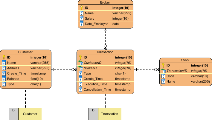
ERDs complement Data Flow Diagrams by representing the structure of information that flows within system processes. While DFDs show how data moves through processes, ERDs define the structure of data stores.

The entities in a physical ERD align with data stores in DFDs, creating a comprehensive view of both data structure and data flow.
BPMN Business Process Diagrams
In business process mapping, ERDs complement BPMN diagrams by representing the structure of data objects needed by business workflows. While BPMN shows how processes utilize data, ERDs define the data objects themselves.


Industry Examples and Case Applications
Movie Rental System
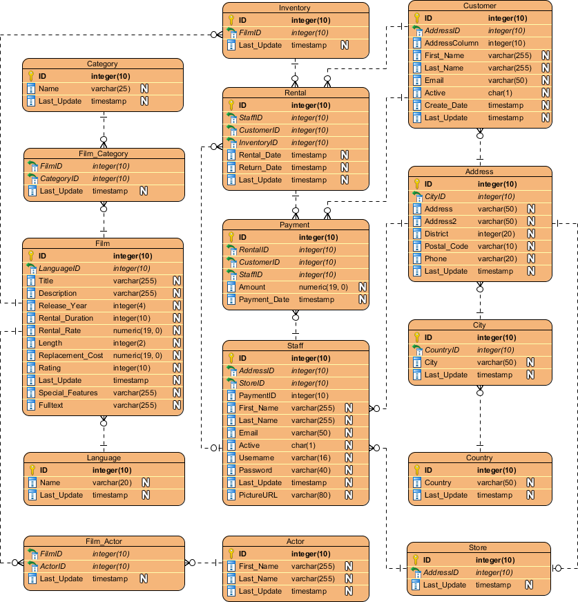
A movie rental system demonstrates complex relationships between customers, rentals, inventory, and payment processing.
Loan System
Financial loan systems require careful modeling of applicants, loans, payments, collateral, and approval workflows.

Online Shop
E-commerce platforms involve intricate relationships between customers, products, orders, inventory, shipping, and reviews.

Best Practices for ERD Development
Creating effective ERDs requires following established best practices:
-
Clarify Purpose: Determine whether you’re creating a conceptual model for business stakeholders or a physical model for database implementation. This decision guides the level of detail required.
-
Define Scope: Clearly establish modeling boundaries to prevent scope creep and redundant entities.
-
Identify Major Entities: Start with the most important business objects before adding supporting entities.
-
Define Attributes: Add columns to entities systematically, considering data types and constraints.
-
Validate Completeness: Review the ERD to ensure all necessary data can be stored. Identify missing transactional, operational, or event entities.
-
Establish Relationships: Connect entities with appropriate cardinality notations, ensuring all relationships are accurately represented.
-
Apply Normalization: Use database normalization techniques to reduce redundancy and improve data integrity. For example, if manufacturer details repeat across product records, create a separate Manufacturer entity linked via foreign key.
Results and Benefits
The implementation of AI-powered ERD generation in OpenDocs delivers measurable benefits across multiple dimensions:
Productivity Gains
Organizations report significant reductions in time spent on initial database modeling. What previously required hours of manual work can now be accomplished in minutes, with AI generating comprehensive first drafts that designers can refine rather than create from scratch.
Improved Accessibility
The natural language interface democratizes database design, allowing business analysts and project managers to contribute to data modeling without deep technical expertise. This bridges the communication gap between business stakeholders and technical teams.
Enhanced Collaboration
By embedding ERDs directly within collaborative documentation spaces, teams maintain a single source of truth. Changes to database designs are immediately visible to all stakeholders, reducing miscommunication and ensuring alignment.
Quality Improvements
AI-powered generation applies consistent design patterns and best practices, reducing common errors such as missing relationships, incorrect cardinality, or normalization violations. Human designers can focus on validation and refinement rather than initial construction.
Knowledge Retention
The integration of ERDs within comprehensive documentation ensures that database designs remain accessible and understandable even as team composition changes. New team members can quickly understand system architecture through visual models embedded in project documentation.
Target Beneficiaries
The enhanced OpenDocs platform with AI ERD generation serves multiple professional roles:
Database Designers & Developers: Rapidly prototype schemas with AI assistance and embed professional diagrams directly in technical documentation.
Software Architects & Analysts: Visualize data structures alongside requirements documents, use case models, and system architecture diagrams.
Project Teams: Maintain consistent, up-to-date data documentation in shared, accessible hubs that support collaboration across distributed teams.
Business Analysts: Translate business requirements into visual data models without requiring deep technical database expertise.
Project Managers: Track database design progress and validate that technical implementations align with business requirements through accessible visual representations.
Technical Considerations
Database Management System Support
Visual Paradigm’s ERD tools support a wide range of popular relational database management systems, ensuring compatibility with organizational technology stacks.

This broad support extends to database design, automated database generation, and ERD reversal (creating diagrams from existing databases).
Tool Accessibility
The ERD designer is available in Visual Paradigm Modeler, providing professional-grade database design capabilities at accessible pricing. The platform offers a 30-day free evaluation period, allowing teams to assess fit before commitment.
Conclusion
The integration of Entity Relationship Diagram support with AI-powered generation capabilities in Visual Paradigm’s OpenDocs platform represents a significant evolution in database design methodology. By combining the power of artificial intelligence with intuitive visual modeling tools, this solution addresses long-standing challenges in database design while opening new possibilities for collaboration and efficiency.
The case study demonstrates that AI-powered ERD generation is not about replacing human expertise but rather augmenting it. The technology handles the time-consuming initial modeling work, interpreting natural language descriptions and applying database design best practices to produce comprehensive first drafts. Human designers then apply their expertise to refine, validate, and optimize these models, focusing their efforts on high-value activities rather than repetitive diagram construction.
The benefits extend beyond mere time savings. By embedding ERDs directly within collaborative documentation platforms, organizations create living knowledge bases where database designs remain contextualized, accessible, and aligned with broader project goals. This integration supports better communication between technical and non-technical stakeholders, reduces the risk of design errors, and accelerates the entire development lifecycle.
As organizations continue to face pressure to deliver complex, data-driven applications more quickly, tools that bridge the gap between business requirements and technical implementation will become increasingly essential. The AI-powered ERD generation capabilities demonstrated in this case study offer a glimpse into the future of database design—one where artificial intelligence and human expertise work in harmony to create better systems faster.
For database designers, software architects, business analysts, and project teams, the message is clear: the future of database design is intelligent, collaborative, and integrated. By embracing these AI-powered tools, organizations can transform database design from a bottleneck into a catalyst for innovation and efficiency.
References
- OpenDocs – AI-Powered Knowledge Management Tool: Comprehensive guide to Visual Paradigm’s AI-powered documentation and knowledge management platform featuring integrated ERD support and AI diagram generation capabilities.
- Visual Paradigm Modeler: Professional visual modeling tool edition featuring comprehensive ERD design capabilities, database generation, and support for multiple database management systems.
- Visual Paradigm Shop: Pricing and purchasing information for Visual Paradigm modeling tools, including subscription options starting at US $6 per month.
- Visual Paradigm Download: Download portal for Visual Paradigm software offering 30-day free evaluation with no credit card required.
- Data Flow Diagram Tool: Visual Paradigm’s DFD tool for visualizing information flow within system processes, complementing ERD modeling for comprehensive system design.
- BPMN Diagram and Tools: Business Process Model and Notation tools for visualizing business workflows and integrating process models with data structure diagrams.
- What is Entity Relationship Diagram: Comprehensive guide covering ERD fundamentals, notation standards, data modeling levels, and best practices for database design.

