


Understanding the behavior of a system is the cornerstone of software engineering. For students entering the field of computer science and information technology, mastering the Unified Modeling Language (UML) is essential. Among the various diagrams available, the Use Case Diagram stands out as a critical tool for defining functional requirements. It bridges the gap between technical specifications and user expectations. This guide provides a deep dive into use case diagram examples, focusing on scenarios relevant to academic work and early-stage development.
Whether you are designing a library system, an e-commerce platform, or a healthcare portal, visualizing interactions is vital. By examining real-world scenarios, you can learn to identify actors, define system boundaries, and map out complex flows without getting lost in the weeds of implementation details.
Why Use Case Diagrams Matter in Student Projects 💡
When starting a capstone project or a semester-long assignment, the scope can easily expand beyond control. A Use Case Diagram serves as a blueprint. It helps you answer fundamental questions before writing a single line of code:
- Who is using the system? (Actors)
- What are they trying to achieve? (Use Cases)
- What is included within the system boundary? (Scope)
This clarity prevents scope creep. It forces you to think about the user experience from a high level. In an academic setting, professors often look for this level of abstraction to verify that you understand the requirements before diving into class diagrams or sequence diagrams.
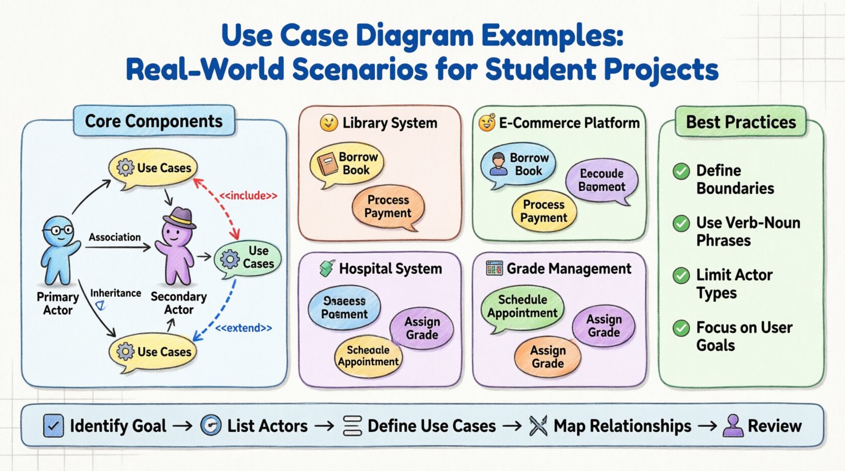
Core Components of a UML Use Case Diagram 🏗️
Before diving into specific examples, it is crucial to understand the building blocks. A well-constructed diagram relies on precise definitions.
1. Actors 👤
An actor represents a role played by an external entity that interacts with the system. It is not necessarily a specific person, but a function or role.
- Primary Actors: Initiates the interaction to achieve a goal. For example, a customer starting a purchase.
- Secondary Actors: Systems or services that the primary actor interacts with, or that support the system. For example, a payment gateway or an external database.
2. Use Cases ⚙️
A use case is a specific goal or function that the system performs. It is usually represented as an oval in the diagram. It describes what the system does, not how it does it.
- Entry Point: Where the interaction begins.
- Exit Point: Where the interaction concludes.
3. Relationships 🔗
Connecting actors and use cases requires understanding specific relationship types:
- Association: A solid line indicating an interaction between an actor and a use case.
- Include: A dashed arrow indicating that one use case incorporates the functionality of another. This is used to avoid redundancy.
- Extend: A dashed arrow indicating an optional behavior that modifies the base use case under specific conditions.
- Generalization: An inheritance relationship where a child actor or use case is a specialized version of a parent.
Example 1: Library Management System 📚
One of the most common projects for students is a Library Management System. It is complex enough to demonstrate relationships but simple enough to manage within a semester.
System Scope
The system manages book inventories, member registrations, and borrowing records. It does not handle the physical logistics of moving books, only the data.
Actors Identified
- Member: The student or reader borrowing books.
- Librarian: The staff member managing the inventory and loans.
- System Administrator: The user managing user accounts and system settings.
Key Use Cases
The following breakdown illustrates the functional requirements:
- Register Book: Adding new items to the inventory.
- Borrow Book: Checking out an item to a member.
- Return Book: Checking in an item.
- Search Catalog: Finding specific titles.
- Manage Membership: Creating or updating user profiles.
Relationship Analysis
In this scenario, the Borrow Book use case might Include a Check Availability use case. This ensures that the borrowing process cannot proceed if the book is not available. This reduces duplication. If you have multiple ways to borrow a book (e.g., via kiosk or desk), both paths can include the same availability check.
The Search Catalog use case can be extended by Reserve Book. If a book is currently borrowed, the member can choose to reserve it. This is an optional action, making it an extension rather than an include.
Example 2: Online Shopping Platform 🛒
E-commerce projects are popular for demonstrating complex workflows and external integrations. This example highlights how to handle multiple user roles and system boundaries.
Actors Identified
- Customer: The end-user browsing and purchasing.
- Vendor: A seller who manages product listings.
- Payment Gateway: An external system handling transactions.
- Inventory System: An external system tracking stock levels.
Key Use Cases
- Search Product: Finding items by category or name.
- Add to Cart: Selecting items for purchase.
- Checkout: Finalizing the transaction.
- Process Payment: Handling the financial transaction.
- Update Inventory: Adjusting stock levels after a sale.
Diagram Structure
The Checkout process is the central flow. It typically Includes Validate Cart and Apply Shipping Address. These are mandatory steps for every checkout.
The Process Payment use case often involves an external actor. The diagram should show the Customer initiating payment, which triggers an interaction with the Payment Gateway. This clarifies that the main system delegates this specific task.
For the Vendor, the use cases differ. They do not check out. Their primary goal is to manage products. Their use cases include List Product and Update Product Details. This separation of concerns is vital for a clean diagram.
Example 3: Hospital Appointment System 🏥
Healthcare systems require high precision regarding data privacy and workflow. This example focuses on access control and complex state changes.
Actors Identified
- Patient: The individual seeking medical attention.
- Doctor: The medical professional managing appointments.
- Receptionist: The staff member handling scheduling and data entry.
- Emergency System: An external alert mechanism.
Key Use Cases
- Book Appointment: Scheduling a visit.
- Cancel Appointment: Removing a scheduled visit.
- View Medical Records: Accessing patient history.
- Prescribe Medication: Issuing a prescription.
- Mark as Emergency: Prioritizing a case.
Complex Relationships
In this system, the View Medical Records use case is restricted. Only the Doctor and the Patient can access it. The Receptionist might have a limited version, such as View Appointment Status. This distinction is represented using Generalization (inheritance) or separate use cases.
The Mark as Emergency use case is an extension of Book Appointment. Under normal circumstances, a patient books a routine visit. If the condition is urgent, the system allows an emergency flag to be raised. This triggers a notification to the Emergency System actor.
Example 4: Student Grade Management System 📊
For a purely academic context, a Grade Management System demonstrates how to handle data flow and permission levels without external dependencies.
Actors Identified
- Student: View grades and submit assignments.
- Instructor: Enter grades and manage courses.
- Registrar: Manage course enrollment and final records.
Key Use Cases
- View Course Schedule: Checking class times.
- Submit Assignment: Uploading work.
- Enter Grade: Recording assessment scores.
- Generate Report Card: Creating official transcripts.
Workflow Logic
The Submit Assignment use case for the Student often has a deadline constraint. If the deadline passes, the use case is no longer available. This logic belongs in the system requirements but can be hinted at in the diagram.
The Generate Report Card use case is a Generalization of View Grades. It requires higher privileges. The Registrar can generate official reports, while the Student can only view their own summary. This hierarchy clarifies security roles.
Comparison of Scenarios 📋
To better understand how these examples differ, consider the following summary table.
| Project Type | Primary Actor | Key Complexity | External Systems |
|---|---|---|---|
| Library System | Member / Librarian | Inventory Logic | None |
| E-Commerce | Customer / Vendor | Transaction Flow | Payment Gateway |
| Healthcare | Patient / Doctor | Privacy & Access | Emergency Alert |
| Grade Management | Student / Instructor | Data Permissions | None |
Best Practices for Designing Your Diagram 🎨
Creating a diagram that is both accurate and readable requires discipline. Avoid common pitfalls that confuse evaluators or developers.
- Define Boundaries Clearly: Draw a box around the system. Everything inside is part of the system; everything outside is an actor. Do not draw actors inside the box unless they are part of the system (e.g., a human-in-the-loop process).
- Use Verb-Noun Phrases: Use Case names should be actions. Write Submit Assignment, not Assignment. This ensures the diagram describes behavior.
- Limit Actor Types: Avoid creating too many specific actors. If you have a Student and a Teacher, and they both access the same course, consider a generic User actor with roles defined elsewhere.
- Group Related Use Cases: If you have many small functions, group them using packages or subsystems to reduce visual clutter.
- Focus on Functional Requirements: Do not include technical details like Database Update or API Call. Those are implementation details. Stick to user goals like Save Data.
Common Mistakes to Avoid 🚫
Even experienced designers make errors. Reviewing these common issues can save you time during the revision process.
- Overcomplicating Relationships: Do not use Extend and Include excessively. If you find yourself nesting them deeply, you are likely mixing implementation logic with functional goals.
- Vague Actors: Avoid labeling an actor as User without specifying the context. A Student is different from an Administrator. Their permissions differ significantly.
- Missing System Boundary: A diagram without a box is ambiguous. It is unclear what the system is responsible for.
- Ignoring Non-Functional Requirements: While Use Case Diagrams focus on function, they should hint at constraints. For example, Process Payment implies security, even if not explicitly drawn.
- Inconsistent Naming: Ensure that the terminology matches the project documentation. If the requirement document says Checkout, do not use Buy Items in the diagram.
Steps to Create Your Diagram 📝
Follow this logical progression to build your diagram effectively.
Step 1: Identify the Goal
Start with the main purpose of the system. What problem does it solve? Write this down as a single sentence.
Step 2: List the Actors
Brainstorm every role that interacts with the system. Ask: Who initiates a request? Who receives information? Who manages the system?
Step 3: Define the Use Cases
For each actor, list the specific goals they want to achieve. Use the verb-noun format.
Step 4: Establish Relationships
Determine how the actors connect to the use cases. Decide if any use cases are mandatory (Include) or optional (Extend).
Step 5: Review and Refine
Walk through the diagram as if you were the user. Does the flow make sense? Are there missing steps? Is the boundary clear?
Integrating with Other UML Diagrams 🔗
A Use Case Diagram is rarely used in isolation. It serves as the entry point for other design artifacts.
- Sequence Diagrams: Once you have a Use Case, you can create a sequence diagram to show the timing of messages between objects.
- Class Diagrams: The nouns found in your Use Case descriptions often become classes in your data model.
- Activity Diagrams: For complex logic within a Use Case, an activity diagram can detail the internal workflow.
Understanding this hierarchy helps you maintain consistency across your documentation. The Use Case Diagram remains the high-level view that aligns stakeholders and developers.
Final Thoughts on Designing Systems 🧠
Creating a Use Case Diagram is an exercise in communication. It translates abstract requirements into a visual language that everyone can understand. For students, it is a skill that demonstrates analytical thinking. It shows you can break down a complex problem into manageable parts.
Focus on clarity over complexity. A simple diagram that accurately reflects the system’s intent is better than a complex one that confuses the reader. By following the examples and best practices outlined here, you will build a foundation for robust system design. Whether you are working on a library app or a hospital portal, the principles remain the same. Identify the actors, define the goals, and map the interactions.
Remember to keep your scope realistic. A diagram that covers every possible edge case is often unmanageable. Focus on the happy paths and the critical exceptions. This approach ensures your project remains achievable within the timeframe of your academic term.
As you progress in your studies, you will encounter more complex systems. The skills you develop now with these examples will scale. You will learn to handle multiple actors, nested logic, and external dependencies with ease. This is the essence of software architecture: organizing chaos into order.
Use this guide as a reference point. Revisit the examples when you feel stuck. Ensure your diagrams are clean, labeled correctly, and aligned with your project requirements. Good luck with your modeling journey.

