


Software development relies on clear communication between stakeholders, designers, and developers. One of the most effective tools for visualizing how a user interacts with a system is the Use Case Diagram. These diagrams provide a high-level view of functionality without getting bogged down in technical implementation details. Whether you are defining requirements for a new application or documenting an existing system, understanding these diagrams is essential for structured design.
This guide explores the fundamentals of modeling system behavior through UML (Unified Modeling Language) use cases. We will break down the components, relationships, and best practices required to create accurate and useful diagrams. By the end, you will understand how to map user interactions clearly and efficiently.
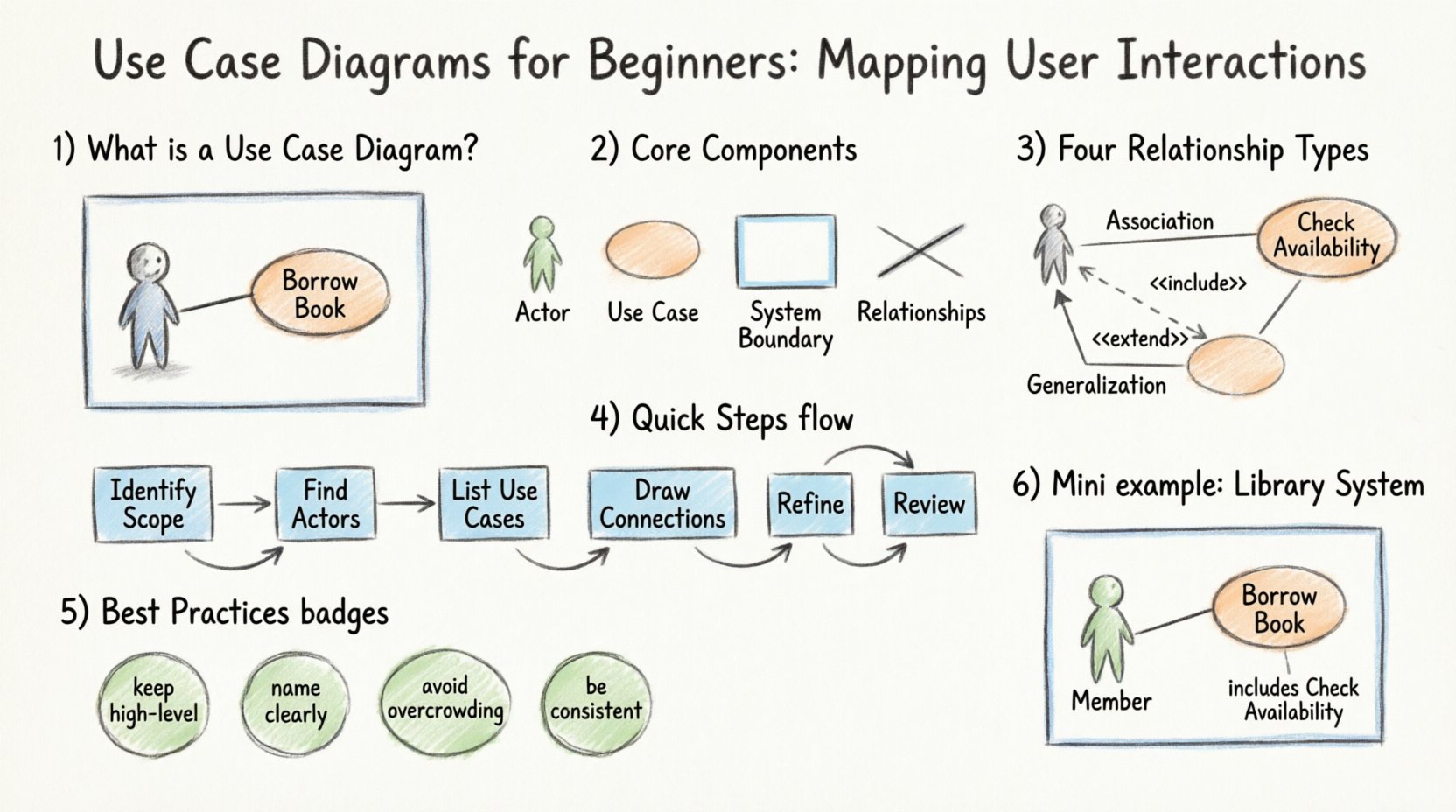
🧩 What is a Use Case Diagram?
A Use Case Diagram captures the functional requirements of a system. It illustrates the interactions between external entities (actors) and the system itself. Unlike detailed flowcharts that show every step of a process, use case diagrams focus on what the system does, not how it does it.
These diagrams serve as a bridge between business needs and technical specifications. They allow stakeholders to verify that the system will meet their needs before any code is written. This visualization helps prevent misunderstandings that often arise during complex software projects.
Key Benefits of Using Use Case Diagrams
- 🔍 Clarifies Scope: Defines the boundaries of the system clearly.
- 🤝 Improves Communication: Provides a common language for developers and business users.
- 📋 Identifies Requirements: Highlights essential features needed for success.
- 🛡️ Reduces Risk: Catches missing functionality early in the design phase.
👥 Core Components of a Use Case Diagram
To create a valid diagram, you must understand the standard symbols and their meanings. UML defines specific shapes for each element. Misinterpreting these symbols can lead to confusion regarding system behavior.
1. Actors 🧑💻
An actor represents a role that interacts with the system. It does not necessarily represent a specific human person. An actor can be:
- A human user with specific permissions.
- Another software system or external service.
- A hardware device that triggers a process.
- A time-based trigger (e.g., a scheduled job running nightly).
Actors are typically drawn as stick figures. They exist outside the system boundary and initiate the interaction. An actor may interact with multiple use cases, and a single use case may involve multiple actors.
2. Use Cases ⚙️
A use case represents a specific goal or function that the system performs. It is a complete unit of functionality from the perspective of an actor. For example, “Place Order” is a use case. “Generate Report” is another.
Use cases are usually drawn as ovals or ellipses inside the system boundary. They are labeled with a verb phrase indicating the action taken.
3. System Boundary 🟦
The system boundary defines the limits of the software being modeled. Everything inside the box belongs to the system; everything outside is external.
- Actors sit outside the boundary.
- Use cases sit inside the boundary.
- Relationships cross the boundary to connect actors to use cases.
Labeling the boundary with the system name provides context for the diagram.
4. Relationships 🔗
Lines connect actors to use cases. These lines indicate communication or interaction. Different types of lines represent different logical connections. Understanding these connections is crucial for accurate modeling.
🤝 Understanding Relationships
Relationships define how actors and use cases interact. There are four primary types of relationships in UML use case modeling. Each serves a distinct purpose in defining system behavior.
| Relationship Type | Symbol | Meaning | Example |
|---|---|---|---|
| Association | Solid Line | Direct communication between actor and use case. | A Customer initiates a Checkout process. |
| Include | Dashed Arrow + <<include>> | A use case must contain the behavior of another use case. | Withdraw Cash always includes Verify PIN. |
| Extend | Dashed Arrow + <<extend>> | A use case adds optional behavior to a base use case. | Apply Discount extends Checkout if a code is entered. |
| Generalization | Solid Line + Triangle | Inheritance. One actor or use case is a specialized version of another. | Admin is a specialized User. |
Deep Dive: Include vs. Extend
These two relationships are often confused. The distinction lies in necessity.
- Include: The included behavior is mandatory. You cannot perform the main use case without performing the included one. Think of it as a sub-task that is always required.
- Extend: The extending behavior is optional. It happens only under specific conditions. It modifies the behavior of the base use case but does not prevent it from running without the extension.
🛠️ Step-by-Step: Creating Your First Diagram
Building a diagram requires a systematic approach. Rushing into drawing shapes without planning leads to cluttered and confusing models. Follow this structured process to ensure clarity.
Step 1: Identify the System Scope
Before drawing anything, define what is inside the system and what is outside. Write down a brief description of the system’s purpose. This helps you decide where to draw the system boundary later.
Step 2: Identify the Actors
List all external entities that interact with the system. Ask questions like:
- Who uses this system?
- What external systems feed data into this system?
- Are there automated processes involved?
Group similar actors if possible. For instance, if there are many types of users with the same permissions, consider creating a generic “User” actor and using generalization to specify roles later.
Step 3: Identify the Use Cases
For each actor, determine what they want to achieve. Focus on goals, not steps. If an actor wants to “Print Report,” that is a use case. “Select Paper Size” is a step within that process, not a separate use case at this level of abstraction.
Step 4: Draw the Connections
Draw solid lines between actors and use cases where interactions occur. Ensure every line makes sense logically. If an actor cannot reach a use case, remove the line.
Step 5: Refine Relationships
Add include and extend relationships where functionality is shared or conditional. Avoid over-complicating the diagram. If a relationship is too complex, consider breaking the use case down into smaller, more manageable parts.
Step 6: Review and Validate
Show the diagram to stakeholders. Ask them if the diagram accurately reflects their understanding of the system. This feedback loop is critical for catching errors before development begins.
✅ Best Practices for Effective Modeling
Creating a diagram is one thing; creating a good diagram is another. Adhere to these principles to maintain clarity and utility.
- 🔹 Keep it High-Level: Use case diagrams are not flowcharts. Do not show every single step. Focus on the goals.
- 🔹 Name Clearly: Use verb-noun phrases for use cases (e.g., “Update Profile”) and clear nouns for actors (e.g., “Registered User”).
- 🔹 Avoid Overcrowding: If a diagram becomes too large, split it into multiple diagrams or subsystems.
- 🔹 Be Consistent: Use the same naming conventions throughout all diagrams in the project.
- 🔹 Focus on Value: Every use case should provide value to an actor. If a use case benefits no one, question its existence.
⚠️ Common Pitfalls to Avoid
Even experienced modelers make mistakes. Being aware of common errors can save you time during reviews.
1. Confusing Use Cases with Processes
A common mistake is treating a use case as a sequence of steps. A use case is a goal. “Place Order” is the goal. The steps to place the order belong in a sequence diagram or a user story, not the use case diagram itself.
2. Including Internal Logic
Do not put internal database operations or screen layouts inside the system boundary as use cases. Use cases must be observable from the outside. A “Save Database Record” action is internal; “Save Customer Data” is the observable goal.
3. Overusing Generalization
While inheritance is useful, too many levels of generalization make the diagram hard to read. Keep the hierarchy shallow. If you need five levels of user types, consider simplifying the roles.
4. Ignoring the System Boundary
Leaving the boundary vague leads to scope creep. Clearly define what is part of the software and what is part of the environment. This prevents developers from building features that are actually external dependencies.
🔄 Use Cases vs. Other Diagrams
Use case diagrams are part of a larger family of modeling tools. Understanding when to use them versus other diagrams is key.
- Sequence Diagrams: Show the order of messages between objects over time. Use these when you need to detail the logic inside a use case.
- Activity Diagrams: Show workflow and decision points. Use these for complex business logic within a specific use case.
- Class Diagrams: Show the static structure of the system (classes, attributes, relationships). Use these for database design and code structure.
- Use Case Diagrams: Show the functional scope and user interactions. Use these for requirements gathering and stakeholder alignment.
📋 Integrating with Requirements Management
A use case diagram is more than a picture; it is a requirement tool. Each use case can be linked to a specific requirement ID in a requirements management tool. This traceability ensures that every feature requested by the business is implemented and tested.
When documenting requirements:
- Create a use case for each major requirement.
- Assign a unique ID to each use case.
- Link the ID to the detailed requirement description.
- Update the diagram if requirements change.
This approach ensures that the diagram evolves with the project. It prevents the documentation from becoming obsolete as the software develops.
🌍 Real-World Scenario Walkthrough
Let us visualize a scenario to solidify these concepts. Imagine a library management system.
Actors
- Librarian: Manages books and members.
- Member: Borrows and returns books.
- System: Automated notifications.
Use Cases
- Search Catalog: Available to both Librarian and Member.
- Borrow Book: Member only.
- Issue Fine: Librarian only.
- Send Reminder: System trigger.
Relationships
- Association: Member connects to “Borrow Book”.
- Include: “Borrow Book” includes “Check Availability”.
- Extend: “Borrow Book” extends “Notify Overdue” if the book is late.
- Generalization: “Staff” generalizes “Librarian”.
This structure allows the team to see exactly who does what without detailing the database queries or UI buttons involved. It keeps the conversation focused on value.
🚀 Moving Forward
Mastering the creation of use case diagrams takes practice. Start with small systems. Focus on accuracy in defining boundaries and actors. As you gain confidence, you can tackle more complex systems with multiple subsystems and external integrations.
Remember that these diagrams are living documents. They should be updated as the system evolves. Keeping them current ensures that new team members can understand the system quickly and that stakeholders remain aligned with the project goals.
By investing time in clear modeling, you reduce ambiguity and build a stronger foundation for software development. Clear diagrams lead to clear code, and clear code leads to reliable systems.

