


In the complex landscape of organizational operations, clarity is currency. Businesses rely on precise documentation to streamline workflows, ensure compliance, and drive efficiency. At the heart of this documentation lies a universal language known as Business Process Model and Notation, or BPMN. This standard provides a visual framework for describing business processes, allowing stakeholders across different departments to understand, analyze, and improve how work gets done.
BPMN is not merely a drawing tool; it is a rigorous specification that bridges the gap between business analysis and technical implementation. By using a standardized set of symbols and rules, organizations can create diagrams that are readable by humans and executable by software. This guide explores the core concepts, elements, and strategic value of BPMN, offering a deep dive for analysts, managers, and technical teams.
Understanding the Core Definition 🏗️
Business Process Model and Notation is a graphical standard for specifying business processes in a business process model. It was originally developed by the Business Process Management Initiative (BPMI) and is now maintained by the Object Management Group (OMG). The primary goal is to create a notation that is intuitive for business users while remaining formal enough to be interpreted by software systems.
Standardization: Unlike proprietary diagramming tools, BPMN offers a global standard. A diagram created in one environment can be understood in another without ambiguity.
Visual Communication: It translates complex logic into visual shapes, making it easier for non-technical stakeholders to validate workflows.
Execution Capability: Modern iterations of the standard allow diagrams to be directly executed by workflow engines, automating processes.
The notation is designed to be extensible. While the core elements remain consistent, organizations can extend the notation to include specific business attributes or technical details required for their unique context.
History and Evolution 📜
The origins of BPMN trace back to the late 1990s and early 2000s, a period when business process management was gaining traction. The need for a common language arose because different software vendors used their own proprietary notations. This fragmentation made it difficult to share models or integrate systems.
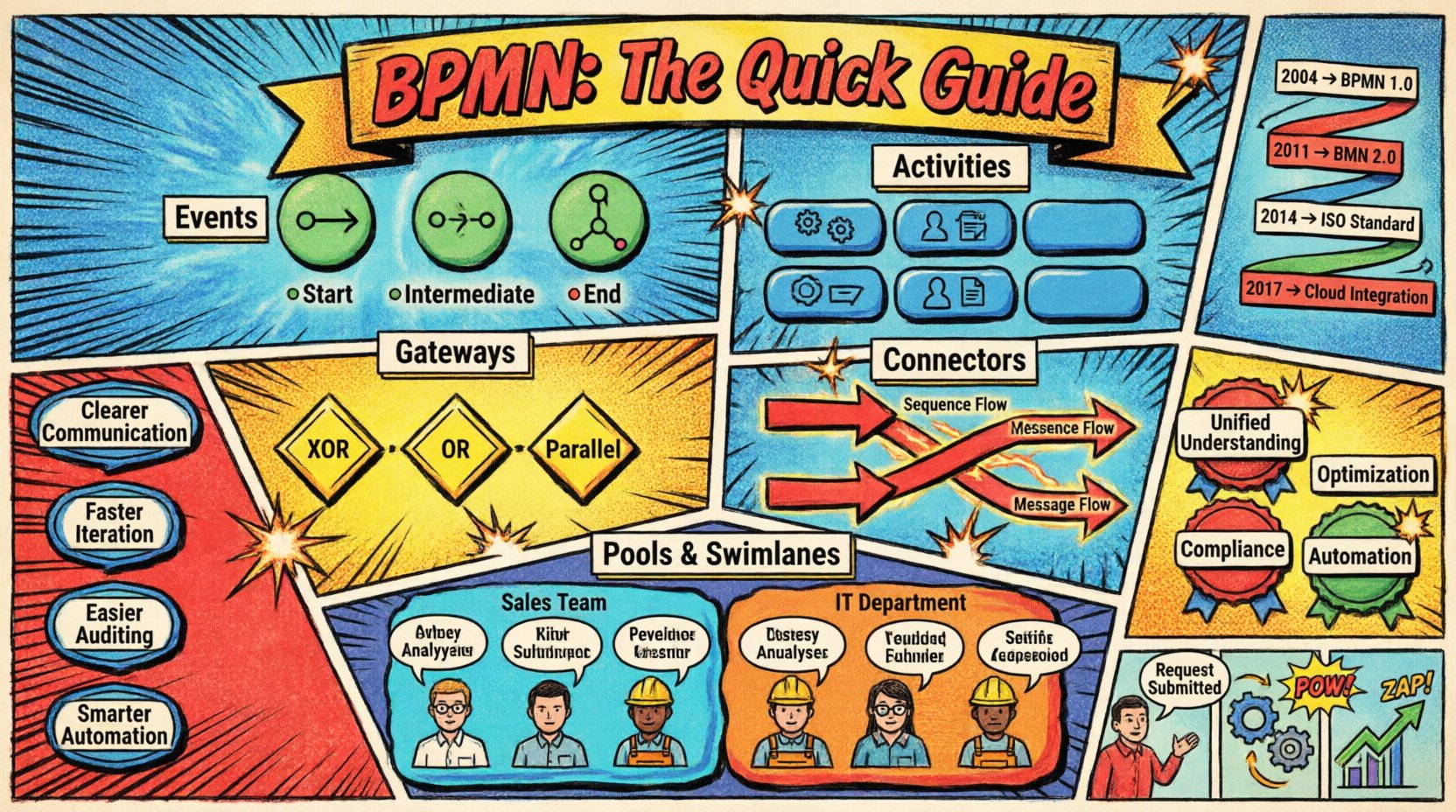
The first version, BPMN 1.0, was released in 2004. It focused primarily on the visual notation aspect. However, the industry quickly recognized the need for a tighter link between the diagram and the underlying code. This led to BPMN 2.0, released in 2011. This version introduced a formal execution model, allowing processes to be defined with the same notation used for design.
Key milestones in the evolution include:
2004: Initial release focusing on visual mapping.
2011: Release of BPMN 2.0, enabling execution and integration.
2014: Update to support mobile devices and better integration with other OMG standards.
2017: Further refinements to improve clarity and reduce ambiguity in complex scenarios.
Core Building Blocks of BPMN 🧩
A BPMN diagram is constructed from four primary categories of elements. Mastering these shapes is essential for creating accurate process models. Each shape carries a specific meaning regarding the flow of control, data, or objects.
1. Events 🟢
Events represent something that happens during the course of a process. They are depicted as circles and are categorized by their behavior at the start, middle, or end of a flow.
Start Events: Indicate where the process begins. They have no incoming flow.
Intermediate Events: Occur in the middle of a process. These can be waiting for a message, a timer, or a signal.
End Events: Mark the termination of a process. A process can have multiple end events depending on different outcomes.
2. Activities 🔵
Activities represent work that is performed within the process. They are shown as rounded rectangles.
Tasks: The smallest unit of work. A task cannot be broken down further within the current model.
Sub-Processes: A group of activities that are treated as a single unit. This allows for hierarchical modeling, where high-level processes can be expanded into detail.
Call Activities: Reference a process defined elsewhere, promoting reuse.
3. Gateways ⬛
Gateways control the divergence and convergence of flow paths. They determine whether the process moves down one path, multiple paths, or waits for specific conditions.
Exclusive Gateway (XOR): Only one path is taken based on a condition.
Inclusive Gateway (OR): One or more paths can be taken simultaneously.
Parallel Gateway: All paths are taken at the same time, splitting the flow into parallel activities.
Event Gateway: Handles complex event-based routing.
4. Connectors 🔗
Connectors link the elements together to show the sequence of operations.
Sequence Flow: Shows the order in which activities are performed. It is represented by a solid line with an arrowhead.
Message Flow: Shows interactions between different participants or pools. It is represented by a dashed line.
Association: Links an artifact or text to an activity.
Visualizing Participants: Pools and Swimlanes 🏊
Processes rarely happen in a vacuum. They involve multiple departments, systems, or external entities. BPMN handles this complexity using Pools and Swimlanes.
A Pool represents a distinct participant in the process. This could be a company, a department, or an external organization. A single process usually has one pool, while interactions with others are shown in separate pools.
Within a pool, Swimlanes divide the activities based on who or what performs them. This adds a layer of responsibility to the diagram.
Element | Function | Visual Representation |
|---|---|---|
Pool | Represents a major participant | Large rectangle containing lanes |
Swimlane | Represents a sub-participant (Role, Dept) | Horizontal or vertical division within a pool |
Message Flow | Communication between pools | Dashed line with open arrow |
Sequence Flow | Order of steps within a lane | Solid line with filled arrow |
Using swimlanes effectively ensures accountability. It clarifies exactly which role is responsible for each step, preventing confusion during execution.
Why Adopt BPMN? Strategic Benefits 🚀
Implementing BPMN is not just about drawing pictures. It is a strategic decision that impacts how an organization operates. The benefits extend beyond documentation into automation and optimization.
Unified Understanding: When business analysts and developers speak the same language, miscommunication decreases. The visual nature of the standard reduces ambiguity in requirements.
Process Optimization: It is difficult to improve what you cannot see. BPMN models expose bottlenecks, redundancies, and unnecessary delays.
Compliance and Audit: In regulated industries, having a clear, standardized record of processes is essential for audits. BPMN provides this traceability.
Automation Readiness: Because BPMN 2.0 defines an execution model, models can often be transformed into executable code, reducing the time from design to deployment.
Change Management: When processes change, the model updates. This makes it easier to communicate changes to the wider organization.
Steps to Create a BPMN Model 🛠️
Creating a robust process model requires a disciplined approach. It is not enough to simply draw shapes; the logic must be sound.
Define the Scope: Identify where the process starts and where it ends. Determine the boundaries to avoid scope creep.
Identify Participants: List all roles, departments, and external systems involved.
Map the Current State: Document how the process actually works today, including workarounds and exceptions.
Design the Future State: Create the ideal workflow, removing inefficiencies and adding necessary controls.
Validate the Model: Walk through the diagram with stakeholders to ensure accuracy. Ask “what if” questions to test logic.
Refine and Deploy: Make adjustments based on feedback and prepare for implementation or automation.
Common Pitfalls to Avoid ⚠️
Even experienced practitioners can fall into traps when modeling processes. Awareness of these common errors helps maintain model quality.
Over-Complexity: Trying to model every detail in one diagram makes it unreadable. Use sub-processes to hide detail where appropriate.
Ignoring Exceptions: A process that only shows the happy path is useless. Always map error handling and alternative flows.
Mixing Levels of Abstraction: Do not mix high-level strategic views with low-level technical steps in the same diagram. Keep them separate.
Unclear Gateways: Ensure every gateway has a clear condition. If a path is not taken, it should be obvious why.
Lack of Context: A diagram without a legend or clear definition of terms can confuse readers. Always include a key if using custom symbols.
Integration with Other Standards 🔄
BPMN does not exist in isolation. It is designed to work in harmony with other modeling standards. This interoperability is crucial for enterprise architecture.
For instance, BPMN often integrates with Business Rule Notation (BRN). This allows rules to be defined separately from the process flow, making them easier to update. Additionally, BPMN aligns with Enterprise Architecture frameworks, ensuring that process models support broader business strategies.
Data modeling is another critical integration point. While BPMN focuses on flow, it must interact with data structures. Understanding how data moves through the process is as important as understanding the control flow.
Best Practices for Documentation 📝
Quality documentation ensures longevity. A model created today should be understandable five years from now.
Consistent Naming: Use clear, concise names for tasks and events. Avoid jargon that might not be understood by all stakeholders.
Logical Flow: Arrange the diagram so the flow reads naturally, typically from top to bottom or left to right.
Color Coding: While standard shapes are black and white, using color to denote status (e.g., red for errors, green for success) can aid readability.
Version Control: Treat process models like code. Maintain versions to track changes over time.
Documentation Notes: Use annotations to explain complex logic that cannot be captured by shapes alone.
The Future of Process Modeling 🌐
The landscape of business process management continues to evolve. As digital transformation accelerates, the need for clear process definitions grows. BPMN remains a cornerstone of this evolution.
Emerging trends include the increased use of AI in process mining. This technology analyzes event logs to compare actual performance against the designed BPMN model. It highlights deviations and suggests optimizations automatically.
Furthermore, the integration of BPMN with low-code platforms is expanding. These platforms allow users to build applications using visual models that are based on BPMN standards. This lowers the barrier to entry for process automation, allowing business users to participate more directly in the implementation phase.
The standard continues to adapt to modern needs, such as cloud computing and mobile interactions. As processes become more distributed, the ability to model interactions across different platforms becomes critical.

