


This guide provides a complete, structured walkthrough of how to interpret, analyze, and create UML Sequence Diagrams, using the “Place Order Scenario” as a practical example. Whether you’re a developer, system analyst, or student, this resource will help you master the key concepts, best practices, and real-world applications of sequence diagrams.
🔍 Overview: What Is a UML Sequence Diagram?
A UML (Unified Modeling Language) Sequence Diagram is a behavioral diagram that shows how objects interact in a specific scenario over time. It captures the order of messages exchanged between objects to achieve a particular goal — in this case, placing and processing an order.
✅ Purpose: Visualize the dynamic behavior of a system — what happens when, in what order, and between whom.
🧩 Core Elements of a Sequence Diagram
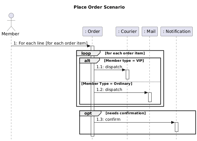
Let’s break down the components of the provided diagram, using the “Place Order Scenario” as our reference.
1. Lifelines (Vertical Dashed Lines)
-
Represent the existence of an object over time.
-
Each object has its own lifeline extending from top to bottom.
-
The object name appears in a rectangle at the top of the line.
📌 Example:
: Order → The Order object exists throughout the process and coordinates actions.
💡 Tip: Use consistent naming (e.g.,
:Orderinstead ofOrder) to distinguish between objects and classes.
2. Actors (Stick Figures)
-
Represent external entities that interact with the system.
-
Typically users, clients, or external systems.
📌 Example:
Member (a stick figure) initiates the process by placing an order.
✅ Key Insight: The first message always comes from an actor — this is the trigger of the scenario.
3. Messages (Horizontal Arrows)
-
Show communication between objects.
-
Arrows are labeled with message names and optional sequence numbers.
📌 Example:
Member -> Order : 1: For each line [for each order item]
→ The Member sends a message to the Order object to begin processing.
🔎 Sequence Numbering:
Use hierarchical numbering like1,1.1,1.2to show logical flow and nesting. This makes diagrams easier to discuss and trace.
4. Activation Bars (Thin Blue Rectangles)
-
Indicate when an object is actively performing a task.
-
They appear on lifelines during method execution or processing.
📌 Example:
When Order receives the message, it activates → shows it’s working.
After dispatching to Courier or Mail, the activation bar ends.
⚠️ Important: Deactivation happens automatically when the object finishes its work (or when
deactivateis explicitly called).
5. Combined Fragments (Control Structures)
These are logical blocks that control the flow of messages. They are essential for modeling complex logic in a single diagram.
| Fragment | Purpose | Equivalent in Code |
|---|---|---|
loop |
Repeats a block of messages | for, while |
alt |
Conditional branching (If-Else) | if-else |
opt |
Optional step (If only condition is true) | if (condition) |
par |
Parallel execution | threads, concurrent tasks |
critical |
Mutual exclusion (locking) | synchronized blocks |
📌 In This Diagram:
🔁 loop for each order item
loop for each order item
    alt Member type = VIP
        Order -> Courier : 1.1: dispatch
    else Member Type = Ordinary
        Order -> Mail : 1.2: dispatch
    end
end
-
For every item in the order, the system decides the delivery method based on the member’s status.
-
This avoids duplicating the same logic for multiple items.
✅ Best Practice: Use
loopto avoid clutter — don’t draw the same message 5 times for 5 items!
🔄 alt (Alternative): Conditional Branching
-
If the member is VIP, send to
Courier. -
Otherwise (Ordinary), send to
Mail.
💬 Note:
altis mutually exclusive — only one branch executes.
📌 opt (Optional): Conditional Step
opt needs confirmation
    Order -> Notification : 1.3: confirm
end
-
Only if
needs confirmationistrue, send a confirmation message. -
This mimics a simple
if (needsConfirmation)block.
✅ Use Case: Ideal for optional notifications, validations, or fallbacks.
📌 Step-by-Step Guide to Reading the Diagram
Follow this structured approach to understand any sequence diagram:
Step 1: Identify the Trigger Actor
-
Look for the first message in the diagram.
-
In this case:
Member -> Order : 1: For each line...
✅ This is the start of the scenario.
Step 2: Trace the Main Flow
-
Follow the messages from top to bottom.
-
Note where activations start and end.
Example Flow:
-
Member sends “For each line” to
Order. -
Orderactivates and loops through each item. -
For each item:
-
If VIP → send
dispatchtoCourier. -
Else → send
dispatchtoMail.
-
-
If
needs confirmation→ sendconfirmtoNotification.
Step 3: Analyze Control Logic
-
Identify
loop,alt,optblocks. -
Understand which conditions trigger which paths.
🧠 Think: “What would happen if the member were not VIP?”
→ The
Step 4: Check for Guards (Conditions in Brackets)
-
[condition]determines whether a message is sent. -
Example:
[for each order item]→ the loop runs per item. -
Example:
[needs confirmation]→ only activates if true.
⚠️ Guard conditions are critical — they define when messages are sent.
🛠️ Best Practices for Creating Effective Sequence Diagrams
Use these principles to ensure clarity, accuracy, and maintainability.
✅ 1. Keep It High-Level
-
Focus on major interactions, not every method call.
-
Avoid modeling low-level details like database queries unless critical.
❌ Don’t do:
Order -> Database : queryUser()
Database -> Order : return user
✅ Do:
Order -> User : fetch details
✅ 2. Use Consistent Naming
-
Match object names to class names in your code or class diagram.
-
Use
:ClassNameformat (e.g.,:Order,:Courier) to indicate objects.
📌 Example:
If your class isOrderService, use:OrderServicein the diagram.
✅ 3. Leverage Combined Fragments for Complexity
Instead of creating 5 different diagrams for:
-
VIP → Courier
-
Ordinary → Mail
-
With/without confirmation
👉 Use one diagram with alt and opt to show all scenarios clearly.
🎯 Result: One diagram replaces multiple, reducing confusion.
✅ 4. Number Messages Strategically
-
Use hierarchical numbering:
1,1.1,1.2,2,2.1, etc. -
Helps in documentation, meetings, and traceability.
📝 Example:
1: Place Order
1.1: Validate items
1.2: Check membership status
2: Confirm order
✅ 5. Use Actors Wisely
-
Only include external users or systems that initiate or receive actions.
-
Don’t add internal components (like
OrderProcessor) as actors.
✅ Actor = External entity (e.g.,
Member,PaymentGateway)
🎯 Real-World Application: The “Place Order” Use Case
* Generated by Visual Paradigm AI Chatbot
Sequence Diagram PlantUML code
@startuml
skinparam style strictuml
title Place Order Scenario
actor Member
participant “: Order” as Order
participant “: Courier” as Courier
participant “: Mail” as Mail
participant “: Notification” as Notification
Member -> Order : 1: For each line [for each order item]
activate Order
loop for each order item
alt Member type = VIP
Order -> Courier : 1.1: dispatch
activate Courier
deactivate Courier
else Member Type = Ordinary
Order -> Mail : 1.2: dispatch
activate Mail
deactivate Mail
end
end
opt needs confirmation
Order -> Notification : 1.3: confirm
activate Notification
deactivate Notification
end
deactivate Order
@enduml
* Generated by Visual Paradigm AI Chatbot
This diagram models a common e-commerce workflow:
| Feature | Diagram Representation |
|---|---|
| Order Processing | Order object controls the flow |
| Delivery Logic | alt based on member status |
| Confirmation | opt based on settings |
| Scalability | loop handles multiple items efficiently |
🌐 Why This Matters:
You can reuse this diagram in:
-
System design documentation
-
Technical interviews
-
Agile user stories (e.g., “As a VIP member, I want my order delivered by courier”)
🧪 Common Mistakes to Avoid
| Mistake | Why It’s Bad | Fix |
|---|---|---|
| Overloading with too many messages | Hard to read and maintain | Focus on key interactions |
| Missing activation bars | Hides active processing | Add activate and deactivate |
Using alt without else |
Implies missing cases | Always define all branches |
| Ignoring guards | Messages may fire incorrectly | Always include [condition] |
Mixing up opt and alt |
Misrepresents logic | opt = optional; alt = choice |
📎 Summary: Key Takeaways
| Concept | Key Point |
|---|---|
| Lifelines | Show object existence over time |
| Actors | External entities that start the process |
| Messages | Communication between objects; use numbering |
| Activation Bars | Show when an object is working |
| Combined Fragments | Model logic: loop, alt, opt |
| Guards | Conditions that control message flow |
| Best Practice | Keep it high-level, use consistent naming, leverage fragments |
📚 Further Learning Resources
-
UML 2.5 Specification – Official standard (www.omg.org/spec/UML)
-
PlantUML Documentation – Great for creating diagrams: https://plantuml.com
-
Books:
-
UML Distilled by Martin Fowler
-
Learning UML 2.0 by Russell C. Miles
-
✅ Final Thought
A good sequence diagram is like a movie script for your system — it tells the story of how objects collaborate to achieve a goal.
Use it to clarify design, communicate with teams, and catch logic flaws early.
📌 Pro Tip: When presenting your diagram, say:
“Let me walk you through the flow: The Member starts the order, the Order object processes each item, decides delivery based on status, and optionally sends a confirmation.”
This makes your diagram clear, compelling, and professional.
📘 You now have everything you need to read, create, and communicate using UML Sequence Diagrams effectively.
Use this guide as your go-to reference for any future design discussions or documentation.
✨ Happy modeling! 🎨
