


Introduction: Navigating the ERD Tool Landscape
For database architects, system analysts, and product managers working with complex data models, selecting the right Entity Relationship Diagram (ERD) tool can significantly impact project velocity and documentation quality. After evaluating numerous database design solutions, Visual Paradigm stands out as a comprehensive platform that bridges the gap between conceptual modeling and production-ready database engineering. This review examines Visual Paradigm’s ERD capabilities from a practitioner’s perspective—focusing on usability, feature depth, collaboration support, and real-world workflow integration—while highlighting both strengths and considerations for prospective users.

Overview: All-in-One Database Engineering
Visual Paradigm positions itself as an integrated solution for database design and implementation. Rather than offering just diagramming capabilities, it supports the full lifecycle: from initial ERD creation to database generation, documentation, and team collaboration.
-
Previous Slide◀︎Next Slide▶︎
-
 Design database in quick with an intuitive ERD tool.
ERD editorERD editor Database table record editor Database view editor
Common Pain Points Addressed
Many database professionals encounter these recurring challenges:
-
Most ERD tools excel at visual modeling but lack robust database generation capabilities.
-
Juggling separate tools for system architecture and database design creates context-switching overhead.
-
Generating professional, shareable database specifications for stakeholder communication remains cumbersome in many solutions.
How Visual Paradigm Responds
Streamlined ERD Authoring
From a user experience standpoint, Visual Paradigm’s drag-and-drop ERD editor reduces the learning curve for creating entities and relationships. Whether modeling one-to-one, one-to-many, or many-to-many relationships, the interface feels intuitive. The tool supports comprehensive notation standards—including entities, stored procedures, functions, views, and relationship connectors—making it suitable for both conceptual brainstorming and physical schema design.
A notable workflow feature: users can maintain traceability across conceptual, logical, and physical models within the same project, which helps preserve design intent as requirements evolve.
Beyond Diagramming: Engineering Capabilities
What distinguishes Visual Paradigm from pure diagramming tools is its bidirectional engineering support:
-
Forward engineering: Generate SQL/DDL scripts directly from ERD models for major DBMS platforms.
-
Reverse engineering: Import existing database schemas to visualize and document legacy systems.
-
Change management: Create patch scripts for iterative design updates, supporting agile database development.
-
ORM code generation: Output object-relational mapping code to accelerate application development.
Collaboration features also merit attention. Teams can publish ERDs to a secure online workspace, enabling stakeholder review with inline commenting. Version control, visual diff comparison, and branch/merge workflows help manage design iterations—features often missing in lighter-weight ERD tools.
Broader Modeling Ecosystem
As an award-winning modeling platform, Visual Paradigm extends beyond database design:
-
System design: UML, SysML, DFD, ORM Diagram, SoaML support
-
Business analysis: BPMN, Customer Journey Maps, EPC, Process Maps
-
Project planning: WBS, Org Charts, Mind Maps, Fishbone diagrams
-
Enterprise architecture: ArchiMate certification by The Open Group
-
UX design: Wireframing, wireflows, and interactive prototyping
This breadth allows teams to maintain modeling consistency across disciplines without switching tools—a significant advantage for cross-functional projects.
Drawing Entity Relationship Diagrams: Practical Workflow
ERD (Entity Relationship Diagram) serves dual purposes: database designers use it to model physical relational structures, while business analysts leverage it to map logical data requirements. Below is a practitioner’s walkthrough of core ERD tasks in Visual Paradigm.
Creating an Entity Relationship Diagram
-
Select Diagram > New from the application toolbar.
-
In the New Diagram window, select Entity Relationship Diagram.
-
Click Next.
-
Enter the diagram name and description. The Location field enables you to select a model to store the diagram.
-
Click OK.
-
This creates an Entity Relationship Diagram. At the top right corner of the diagram, select the Data Model. All entities created in this diagram will be set to the chosen data model. And note that only entities in physical model will be included in generating database/DDL.
Drawing an Entity
To draw an entity, select ![]() from the diagram toolbar and then click on the diagram. An entity will be created.
from the diagram toolbar and then click on the diagram. An entity will be created.
 |
|---|
| Entity created |
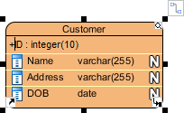
Adding Columns to Entities
To add column into entity:
-
Right click on the entity and select New Column from the popup menu.
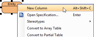
To create a new column -
A column is added. Enter its name in the pattern COL_NAME : COL_TYPE where COL_TYPE is the data type of column.
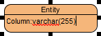
Naming a new column -
Press Enter to confirm.
-
Now, you can repeat step 2 and 3 to add more columns. When finished editing, press Esc to confirm.
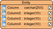
Columns created
Modeling MySQL ‘Set Type’
SET columns in MySQL allow definitions of columns containing a predefined set of values. In Visual Paradigm you can model a set type with these steps:
-
Add a column into the entity.
-
Right click on the column and select Open Specification… from the popup menu.
-
Select varchar to be the Type of column.
-
Enter the definition statement in the User type field, in pattern SET(‘a’,’b’,’c’, …) where ‘a‘, ‘b‘, ‘c‘… are the allowed values of this column.
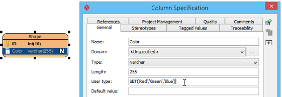
Defining user type NOTE: The User type field is only available when the DBMS selected in database configuration supports the definition of user type. E.g. MySQL. -
Click OK to confirm. Note that the definition will also be effective in database and DDL exporting.
Specifying Primary Keys
There are several ways to specify a column as a primary key. When inline editing, you can type + before the column name to indicate that the column is a primary key column.
 |
|---|
| Specifying a primary key |
Alternatively, right click on a column and select Include in Primary Key to set the column as primary key or include it as part of a composite key. Finally, you can also find and check the Include in Primary Key option in the Column Specification window. To open the window, right click on a column and select Open Specification… from the popup menu.
Clustered and Non-Clustered Primary Keys
The use of clustered primary key may make the querying of data more efficient. To make a primary key of an entity a clustered/non-clustered primary key:
-
Right click on that entity and select Open Specification… from the popup menu.
-
Open the Columns tab.
-
Select Clustered/Non-Clustered for Primary key clustered.
-
Click OK.
Hiding Nullable Icons in ERD
In case you want to hide the nullable icon (as represented by symbol N) in ERD, you can follow the steps below: Right click on the diagram > Presentation Options > Entity Columns Display Options> Column Constraints Presentation Option> uncheck Show Nullable.
Selecting All Columns in an Entity
To select all columns within an entity, select any column first, and then press Ctrl-A to select the rest.
Working with Relationships
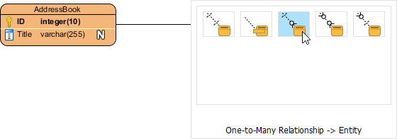
Creating an Entity with Relationship
Relationship shows how the entities are related to each other. You can create a related entity by performing the steps below:
-
Move your mouse pointer over the source entity.
-
Press on the Resource Catalog button and drag it out.

Using Resource Catalog -
Release the mouse button at the place where you want the entity to be created.
-
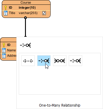
In Resource Catalog, select the kind of relationship to be created. If you want to create an entity with a one-to-many relationship, select One-to-Many Relationship -> Entity.
To create an entity -
You should see the entity now and it is connected to the source entity. Enter its name and press Enter to confirm editing.
Entity created
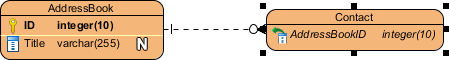
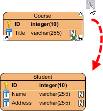
Connecting to Existing Entities
To connect to an existing entity:
-
Move your mouse pointer over the source shape.
-
Press on the Resource Catalog button and drag it out.
Using Resource Catalog -
Release the mouse button at the target entity.
-
In Resource Catalog, select the kind of relationship to be created.
To create a one-to-many relationship between entities The entities are now connected with the relationship you chose.
Linked Entities in Many-to-Many Relationships
When you create a many-to-many relationship, a linked entity will be created, with two one-to-many relationships connected to it from the source entities.
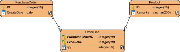 |
|---|
| Linked entity |
Identifying and Non-Identifying Relationships
There are two types of relationships – identifying and non-identifying.
-
Identifying relationship: Specifies the part-of-whole relationship. The child instance cannot exist without the parent instance. Once the parent instance is destroyed, the child instance becomes meaningless.
-
Non-identifying relationship: Implies weak dependency between parent and child entities. Includes optional and mandatory variants, where the necessity of the parent entity is “exactly one” (mandatory) or “zero or one” (optional).
AI-Powered Enhancements: Accelerating Schema Design
Visual Paradigm has integrated AI capabilities to streamline ERD creation, particularly valuable for rapid prototyping or requirements exploration.
Key AI Features
-
Text-to-ERD Generation: Describe data requirements in plain language; the DB Modeler AI suggests entities, attributes, primary keys, and foreign key relationships.
-
Notation Flexibility: AI generation supports standard ERD notation and Chen Notation for detailed conceptual modeling.
-
AI Chatbot Assistance: An intelligent assistant helps refine requirements and transform them into live database prototypes.
Platform Availability
-
Visual Paradigm Online: Cloud-based environment for rapid AI-powered prototyping.
-
Visual Paradigm Desktop: Advanced AI features available when connected to a Visual Paradigm Online workspace.
-
OpenDocs: AI-powered documentation tool that supports ERD generation and embedding directly into project documentation.
Core ERD Capabilities Beyond AI
For teams preferring manual control or working with legacy systems, Visual Paradigm provides robust traditional features:
-
Reverse Engineering: Import and visualize existing database schemas.
-
DDL Code Generation: Export production-ready SQL scripts for major DBMS platforms.
-
Data Dictionary Synchronization: Keep ERD models and data dictionaries in sync as designs evolve.
Conclusion: Who Should Consider Visual Paradigm for ERD Work?
Visual Paradigm’s ERD toolset is best suited for:
✅ Enterprise teams needing end-to-end database engineering with collaboration and version control
✅ Consultants and architects who require professional documentation and stakeholder communication features
✅ Cross-functional projects where database design intersects with system modeling, business analysis, or UX workflows
✅ Teams adopting AI-assisted design who want to accelerate schema prototyping without sacrificing control
Considerations: The platform’s breadth may introduce a steeper initial learning curve compared to lightweight diagramming tools. Organizations with simple, one-off ERD needs might find the feature set more extensive than required. However, for professionals managing complex, evolving data architectures, Visual Paradigm’s integrated approach—combining intuitive visual modeling, engineering automation, AI assistance, and team collaboration—delivers tangible efficiency gains and documentation quality that justify the investment.
For database practitioners seeking a single environment to design, validate, generate, and share data models, Visual Paradigm represents a mature, feature-rich option worth evaluating in your toolchain assessment.
References
- Visual Paradigm ERD Tool Solution: Comprehensive overview of Visual Paradigm’s Entity Relationship Diagram capabilities for database design and engineering.
- Database Design with ERD Tools: Feature showcase highlighting intuitive ERD editing, database generation, and professional specification output.
- OpenDocs ERD AI Generation Release: Announcement of AI-powered ERD generation capabilities integrated into Visual Paradigm’s documentation platform.
- AI Diagram Generation Features: Details on AI-assisted diagram creation, including text-to-ERD functionality and intelligent modeling suggestions.
- Visual Paradigm ERD Tool (Traditional Chinese): Traditional Chinese language resource for ERD tool features and solutions.
- Chen ERD Editor Feature: Specialized support for Chen notation in Entity Relationship Diagrams for conceptual data modeling.
- AI Diagram Generator Update: DFD & ERD: Release notes covering expanded AI diagram generation support for Data Flow Diagrams and ERDs.
- Visual Paradigm ERD Tool (Simplified Chinese): Simplified Chinese language resource for ERD tool capabilities and implementation guidance.
- Visual Paradigm Product Shop: Official storefront for Visual Paradigm licensing, editions, and purchase options.
- Click Start AI Technical Guide: Step-by-step instructions for enabling and using AI features within Visual Paradigm Desktop.
- Archimetric Guide to Visual Paradigm OpenDocs: Third-party developer guide covering AI-powered documentation workflows with ERD integration.
- AI Process Overview: Diagram Generator: Official guide explaining the AI diagram generation workflow, best practices, and use cases.
- Guide: What is an Entity Relationship Diagram: Foundational educational resource explaining ERD concepts, notation, and modeling principles.
- Tutorial: Data Modeling and Data Dictionary: Practical tutorial on synchronizing ERD models with data dictionaries for consistent documentation.