


The C4 model is a powerful, human-readable approach to software architecture documentation. It helps teams visualize the system’s context, scope, and relationships with external actors and systems. Visual Paradigm offers an AI-powered C4 Diagram Tool that simplifies the creation of System Context Diagrams, enabling rapid prototyping and iteration. This guide walks you through every step—from setting up your project to refining and sharing your diagram—using both AI-generated and manual methods.
🔷 What Is a C4 System Context Diagram?
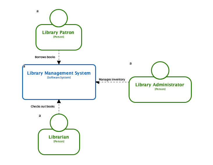
A C4 System Context Diagram is the first level of the C4 model. It provides a high-level view of:
-
The core system (your software application),
-
Actors (users or external systems interacting with it),
-
External dependencies (other systems the core system interacts with).
It focuses on scope and relationships, not internal implementation details—making it ideal for stakeholder communication and early design discussions.
🛠️ Prerequisites
Before you begin, ensure you have:
-
Visual Paradigm installed (Desktop or Online version).
-
An active internet connection (required for AI features).
-
A clear understanding of your system’s purpose and key interactions.
✅ Tip: The AI-powered C4 tool works best when your description is specific and includes key actors, the system name, and notable external dependencies.
✅ Step-by-Step Guide to Creating a C4 System Context Diagram
Step 1: Start a New Project
-
Open Visual Paradigm (either desktop or online).
-
Click “New Project” from the welcome screen.
-
Choose a project type (e.g., “Software Project”) and give your project a name (e.g., “Online Banking System”).
💡 Pro Tip: Use descriptive names to help organize your architecture documentation.
Step 2: Access the C4 Diagram Tool
-
Go to the Diagram menu and select “New”.
-
In the search bar, type “C4”.
-
Select “System Context Diagram” from the list of available diagrams.
A blank canvas will appear with the C4 diagram template ready for use.
Step 3: Generate Diagram with AI (Fastest Method)
This is the most efficient way to get started—especially during early design phases.
✅ How to Use the AI Assistant:
-
Open the AI Assistant (usually located in the sidebar or via a chat icon).
-
Enter a clear, concise description of your system. For example:
“Create a system context diagram for a banking system where customers can view accounts, transfer money, and receive email notifications. The system integrates with an external email service and a payment gateway.”
-
Click “Generate”.
📌 What the AI Produces:
-
A pre-populated diagram with:
-
A Person actor labeled as “Customer”.
-
A Software System representing your core system (e.g., “Online Banking System”).
-
External Systems such as “Email Service” and “Payment Gateway”.
-
Connectors showing relationships (e.g., “uses”, “sends email to”).
-
-
All elements are editable—you can modify labels, add descriptions, or change relationships.
🔍 Note: The AI may occasionally misinterpret complex or ambiguous inputs. Always review and validate the output.
Step 4: Manual Creation (Alternative or for Refinement)
If you prefer full control or want to refine the AI-generated diagram:
-
Use the palette on the left side of the editor:
-
Drag a Person icon to represent an actor (e.g., “Customer”).
-
Drag a Software System icon to represent your core system.
-
Drag External System icons for third-party services (e.g., “Email Service”, “Credit Card Processor”).
-
-
Use connectors to define relationships:
-
Right-click on a shape → Select “Create Connector”.
-
Choose the appropriate relationship type (e.g., “Uses”, “Sends Email To”, “Communicates With”).
-
-
Label each connector clearly:
-
Example: “Customer → Online Banking System: Logs in and views account balance”
-
✅ Best Practice: Use natural language for connector labels to improve readability.
Step 5: Refine and Enhance Your Diagram
Once the basic structure is in place, enhance clarity and usefulness:
✏️ Add Descriptions:
-
Double-click any element to open its properties.
-
Add a description explaining the role or function (e.g., “Handles user authentication and transaction processing”).
⚙️ Specify Technology (Optional):
-
Add tags or notes to indicate technologies used (e.g., “Built with Node.js”, “Uses AWS S3 for storage”).
🔄 Iterate with AI:
-
Reuse the AI assistant to update your diagram:
-
Example prompt: “Remove the email service dependency and replace it with SMS notifications.”
-
The AI will regenerate the diagram accordingly.
-
✅ Tip: Use iterative prompts to evolve your diagram as requirements change.
Step 6: Export and Share Your Diagram
After finalizing your diagram, export it for sharing or documentation:
-
Go to File > Export.
-
Choose your desired format:
-
PNG – For presentations or reports.
-
PDF – For formal documentation or stakeholder handouts.
-
SVG – For scalable vector graphics (ideal for web use).
-
-
Save the file or copy the image directly into your documentation.
📎 Bonus: You can also save the project to continue working on it later or collaborate with team members.
🎯 Key Tips for Success
| Tip | Description |
|---|---|
| Keep It Simple | Focus on high-level scope. Avoid technical details like databases or APIs. |
| Use Clear Labels | Ensure actors, systems, and relationships are self-explanatory. |
| Iterate with AI | Use AI to generate, modify, or regenerate diagrams quickly. |
| Validate AI Output | Always double-check generated diagrams—AI can make assumptions or omissions. |
| Document Assumptions | Add a note or legend if your diagram includes assumptions (e.g., “Assumes OAuth 2.0 for login”). |
🧠 Why Use AI for C4 Diagrams?
Visual Paradigm’s AI-powered C4 PlantUML Studio accelerates architectural modeling by:
-
Reducing time spent on initial diagram creation.
-
Supporting natural language input for non-technical stakeholders.
-
Enabling rapid iteration and versioning.
-
Integrating seamlessly with the full C4 model (Container, Component, and Code diagrams).
🌐 Learn more: AI-Powered C4 PlantUML Studio
📚 Reference List (Markdown Format)
- C4 Diagram Tool – Visual Paradigm: A comprehensive overview of the C4 Diagram Tool in Visual Paradigm, including features, use cases, and integration with AI.
- How to Generate a C4 Diagram Using AI Assistant (YouTube Video): A step-by-step video tutorial demonstrating how to use the AI assistant in Visual Paradigm to generate a C4 System Context Diagram.
- C4 PlantUML Studio – Visual Paradigm: Detailed information about the C4 PlantUML Studio, which supports automated diagram generation and integration with PlantUML syntax.
- AI-Powered C4 PlantUML Studio – Visual Paradigm: Official documentation on the AI-driven C4 diagram generation tool, highlighting its capabilities and workflow.
- C4 System Context Diagram – A Definitive Guide to Seeing the Big Picture with AI: A detailed guide explaining the purpose, structure, and best practices for creating C4 System Context Diagrams using AI.
- Beginner’s Guide to C4 Model Diagrams – Visual Paradigm Blog: An accessible introduction to the C4 model, covering all four levels and their practical applications.
- Visual Paradigm Full C4 Model Support – Release Notes: Official release notes highlighting the addition of full C4 model support in Visual Paradigm, including context, container, component, and code diagrams.
- C4 Model Tool – Visual Paradigm Online: Features and capabilities of the C4 model tool available in the online version of Visual Paradigm, ideal for remote teams and collaborative design.
📝 Final Thoughts
Creating a C4 System Context Diagram in Visual Paradigm is now faster, smarter, and more accessible than ever—thanks to AI integration. Whether you’re using the AI assistant for rapid prototyping or manually crafting a detailed diagram, the C4 model helps ensure that your software architecture is clearly communicated to developers, stakeholders, and business teams alike.
Start simple. Iterate often. Let AI do the heavy lifting—but always verify the results.
✅ Now You’re Ready to Build Clear, Scalable, and Collaborative Architecture Diagrams!
