


In today’s digital banking era, Automated Teller Machines (ATMs) are critical touchpoints between financial institutions and their customers. To ensure reliability, security, and scalability, modern ATM systems are built using robust object-oriented design principles. This article presents a detailed architectural overview of an ATM system based on a well-structured class diagram, emphasizing modularity, separation of concerns, and real-world hardware-software integration.
We’ll explore the core components, relationships, transaction workflows, and user interactions that define this system — culminating in a practical guide to modeling it using Visual Paradigm, a leading UML modeling tool.
🔷 1. Core Banking Entities: The Foundation of Trust
At the heart of any banking system lies the Bank, which acts as the central authority governing all transactions and user validation. In this design, Bank is defined as an abstract class, enabling future specialization for different financial institutions (e.g., BankA, BankB) while maintaining a consistent interface.
Key Entities:
-
Bank(Abstract Class)-
Responsibilities:
validateCard(cardNumber: String): Boolean,validatePIN(customerID: String, pin: String): Boolean -
Purpose: Centralizes authentication logic, ensuring secure access to customer accounts.
-
-
Customer(Stereotyped as «entity»)-
Represents a real-world user with a unique identity.
-
Associated with one or more
Accountinstances via a 1-to-many relationship.
-
-
Account(Stereotyped as «entity»)-
Holds financial data such as
balance,accountNumber, andaccountState. -
The
accountStateis managed through an enumeration:-
Active: Account is operational. -
Blocked: Temporarily locked due to failed PIN attempts (security measure). -
Closed: Permanently deactivated (e.g., by customer request).
-
-
-
Card-
Physical credential used to initiate a session.
-
Attributes:
cardNumber,expirationDate, and optionallycvv. -
Tied to a
Customerand linked to one or moreAccountobjects.
-
✅ Design Insight: The use of an abstract
Bankclass allows for extensibility — new banks can be added without modifying existing ATM logic, promoting open/closed principle compliance.
🔷 2. ATM Hardware Components: A Composite Machine
The ATM is not just a software interface — it’s a physical machine composed of specialized hardware. The class diagram reflects this reality through composition and aggregation relationships.
Core ATM Components:
-
ATM(Main Controller Class)-
Attributes:
atmId,location(e.g., city, street, GPS coordinates) -
Acts as the orchestrator of all operations and hardware interactions.
-
-
Card Reader(Aggregation)-
Responsible for reading the magnetic stripe or chip on the customer’s card.
-
Aggregated by the
ATM— meaning it can exist independently but is logically part of the ATM system.
-
-
Cash Dispenser(Composition)-
A critical component with a composition relationship to the
ATM. -
If the ATM is destroyed or decommissioned, the dispenser is also removed.
-
Handles the mechanical release of banknotes based on transaction validation.
-
⚠️ Composition vs Aggregation:
Composition (Cash Dispenser): Life cycle tied to the ATM. Cannot exist independently.
Aggregation (Card Reader): Can be swapped or replaced without affecting the ATM’s core structure.
This distinction ensures that hardware dependencies are modeled accurately, supporting maintenance planning and fault isolation.
🔷 3. Transaction Logic: Separation of Concerns
To maintain clean, testable, and extensible code, the system separates transaction types from execution logic using interfaces and specialized classes.
The Transaction Interface
«interface» Transaction
{
    Boolean execute();
}
This interface defines a universal contract: every transaction must implement execute() and return a boolean indicating success or failure.
Specialized Transaction Classes
| Class | Responsibility |
|---|---|
Withdrawal |
Validates account balance, checks for sufficient funds, triggers the Cash Dispenser, and updates the account. |
Deposit |
Accepts cash or checks via the deposit slot, verifies integrity, updates account balance, and logs the event. |
Balance Inquiry |
Retrieves and displays current account balance (no hardware interaction). |
Transfer |
Facilitates fund movement between accounts (may involve multiple validations). |
💡 Key Feature: The
Withdrawalclass directly depends on theCash Dispenser— illustrating how business logic drives hardware control.
Transaction Logging
-
TransactionLog-
Implements the
«interface» Transactionto record every transaction. -
Stores logs such as: timestamp, transaction type, amount, account ID, and outcome.
-
Supports audit trails, fraud detection, and reconciliation.
-
✅ Best Practice: Using interface realization here enables logging to be decoupled from transaction execution — a classic example of dependency inversion.
🔷 4. User Interaction and Security: Bridging Human and Machine
Security and usability are paramount in ATM systems. The architecture ensures that interactions are both secure and intuitive.
User Interface Layer
-
UserInterface(«interface»)-
Defines standard methods for user communication:
-
displayWelcome() -
promptPin() -
showBalance(balance: Double) -
displayMessage(message: String)
-
-
Allows for multiple implementations:
-
Touchscreen UI
-
Voice-guided interface (for accessibility)
-
Text-only display (legacy systems)
-
-
🔐 Security Implication: The interface ensures that sensitive prompts (like PIN entry) are handled uniformly across all ATM models, reducing the risk of insecure input handling.
Maintenance Staff (Librarian)
Despite the name “Librarian” — which originates from older templates — this role represents Maintenance Staff or ATM Operators.
-
Role: Perform tasks like:
-
Refilling cash in the dispenser
-
Replacing card readers
-
Checking system logs
-
Performing software updates
-
-
Dependency: Has a usage dependency on
TransactionandDepositmodules to verify transaction integrity during maintenance checks.
🛠️ Operational Insight: This dependency allows staff to validate system health without full access to customer data, adhering to the principle of least privilege.
🔷 5. Relationship Summary: Understanding the Structure
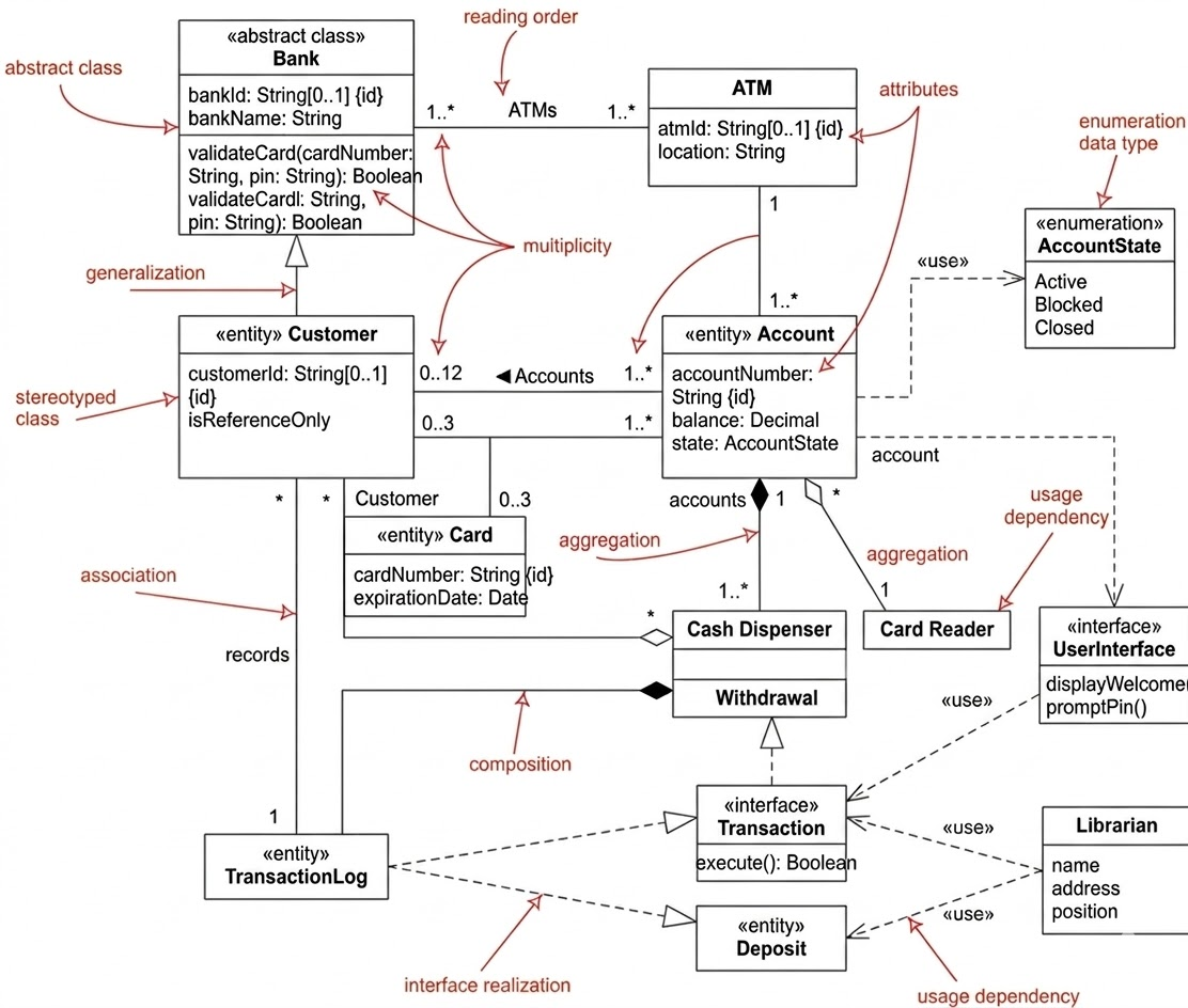
The class diagram uses several UML relationships to model real-world dependencies accurately. Here’s a breakdown:
| Relationship Type | Example | Meaning |
|---|---|---|
| Generalization | Customer → User (if defined) |
Inheritance; Customer is a specialized type of user. |
| Composition | ATM ————→ Cash Dispenser |
Whole-part relationship; dispenser cannot exist without ATM. |
| Aggregation | Bank ————→ ATM |
“Has-a” relationship; ATMs are part of the bank network but can exist independently. |
| Multiplicity | 1 Bank ————→ 1..* ATMs |
One bank manages one or more ATMs. |
| Dependency | MaintenanceStaff → Transaction |
Staff uses transaction logic for system checks. |
| Interface Realization | TransactionLog ————→ Transaction |
Log records all transactions via interface. |
📊 Visual Tip: Multiplicity constraints like
1..*and0..1help prevent invalid data states (e.g., an ATM without a bank).
📊 Would You Like a Sequence Diagram?
Yes — a sequence diagram would be highly beneficial to visualize the flow of a Withdrawal transaction from start to finish. Here’s a preview of what it would show:
🔁 Withdrawal Sequence (High-Level Flow):
-
User inserts card →
CardReaderreadscardNumber. -
ATMsendsvalidateCard(cardNumber)toBank. -
Bankreturnstrue(valid card). -
UserInterfaceprompts for PIN. -
ATMsendsvalidatePIN(customerID, pin)toBank. -
Bankconfirms PIN is correct. -
ATMretrieves the account and checksaccountState. -
User selects “Withdrawal”, enters amount.
-
Withdrawalchecks ifbalance >= amount. -
If yes →
CashDispenserreleases cash. -
Accountbalance is updated. -
TransactionLogrecords the event. -
UserInterfacedisplays success message.
This sequence demonstrates modular design, security checks, and hardware-software coordination — all critical in real-world ATM operation.
✅ Next Step: Let me know if you’d like me to generate this full sequence diagram (in text or as a visual description) for your documentation or presentation.
🛠️ Tooling Section: Modeling the ATM System with Visual Paradigm
To bring this architecture to life, you can use Visual Paradigm, a powerful UML modeling tool that supports class diagrams, sequence diagrams, and code generation.
✅ Step-by-Step: Creating the ATM Class Diagram in Visual Paradigm
1. Launch Visual Paradigm
-
Open the application and create a new UML project.
-
Select Class Diagram from the template list.
2. Add Core Classes
-
Use the Class tool to add:
-
Bank(set as abstract) -
Customer,Account,Card,ATM,TransactionLog
-
-
For
Account, create an enumeration forAccountState:-
Right-click on the diagram → Add → Enumeration
-
Define values:
Active,Blocked,Closed
-
3. Define Relationships
-
Generalization: Draw a hollow triangle from
Customerto a baseUserclass (if needed). -
Composition: Use a filled diamond on the
ATMside connected toCashDispenser. -
Aggregation: Use a hollow diamond from
BanktoATM. -
Associations: Draw lines between
CustomerandAccount,AccountandCard, etc. -
Add multiplicity labels: e.g.,
1onBank,1..*onATM.
4. Add Interfaces
-
Use the Interface tool to create:
-
Transaction -
UserInterface
-
-
Use realization (dashed line with open triangle) from
Withdrawal,Deposit,TransactionLogtoTransaction.
5. Add Dependencies
-
Use the Dependency tool to connect:
-
MaintenanceStaff→Transaction -
MaintenanceStaff→Deposit
-
6. Generate Code (Optional)
-
Right-click on any class → Generate Code.
-
Choose language (Java, C#, etc.).
-
Visual Paradigm will generate skeleton classes with methods and attributes based on your diagram.
7. Export & Share
-
Export the diagram as:
-
PNG/SVG (for reports)
-
PDF (for documentation)
-
HTML (for web-based documentation)
-
-
Use “Generate Documentation” feature to create a full technical specification.
🎯 Pro Tips:
Use stereotypes (
«entity»,«interface») via the Stereotype dropdown in the property panel.Group related classes using packages (e.g.,
Banking,Hardware,Transactions).Enable auto-layout to organize the diagram neatly.
✅ Conclusion
This ATM system architecture exemplifies modern object-oriented design at its best:
-
Modularity: Each component has a single responsibility.
-
Extensibility: Abstract classes and interfaces allow for easy expansion.
-
Security: PIN and card validation are centralized and auditable.
-
Hardware Integration: Composition and aggregation model real-world dependencies accurately.
-
Maintainability: Clear separation between UI, business logic, and hardware.
With tools like Visual Paradigm, developers and architects can model, validate, and communicate this complex system with clarity and precision — ensuring that every transaction is secure, reliable, and traceable.
📌 Final Thought:
A well-designed class diagram isn’t just a drawing — it’s a blueprint for a secure, scalable, and maintainable banking system. Use it to guide development, train teams, and ensure quality from day one.
UML Class Resource
- What Is a Class Diagram? – A Beginner’s Guide to UML Modeling: This resource provides an informative overview explaining the purpose, components, and importance of class diagrams in software development and system design.
- Complete UML Class Diagram Tutorial for Beginners and Experts: A step-by-step guide that walks users through the process of creating and understanding diagrams to master software modeling.
- AI-Powered UML Class Diagram Generator by Visual Paradigm: This advanced tool utilizes artificial intelligence to automatically generate UML class diagrams from natural language descriptions, streamlining the design process.
- From Problem Description to Class Diagram: AI-Powered Textual Analysis: This article explores how AI can convert natural language problem descriptions into accurate class diagrams for efficient software modeling.
- Learning Class Diagrams with Visual Paradigm – ArchiMetric: An article highlighting the platform as an excellent choice for developers to model the structure of a system in object-oriented design.
- How to Draw Class Diagrams in Visual Paradigm – User Guide: A detailed technical guide explaining the step-by-step software process of creating class diagrams within the environment.
- Free Online Class Diagram Tool – Create UML Class Diagrams Instantly: This resource introduces a free, web-based tool for building professional UML class diagrams quickly without local installation.
- Mastering Class Diagrams: An In-Depth Exploration with Visual Paradigm: A comprehensive guide that provides an in-depth technical exploration of class diagram creation for UML modeling.
- Class Diagram in UML: Core Concepts and Best Practices: A video tutorial that explains how to represent the static structure of a system, including attributes, methods, and relationships.
- Step-by-Step Class Diagram Tutorial Using Visual Paradigm: This tutorial outlines the specific steps needed to open the software, add classes, and build a diagram for system architecture.
