


The C4 Model is a widely adopted approach to software architecture documentation, offering a structured way to visualize systems at increasing levels of detail. At its foundation lies the System Landscape Diagram (Level 0), which provides the highest-level, enterprise-wide view of all software systems within an organization. This guide walks you through the complete process of creating a C4 System Landscape Diagram in Visual Paradigm using the AI-powered C4 Model Generator, ensuring clarity, accuracy, and alignment with best practices.
🔷 What Is a C4 System Landscape Diagram?
The System Landscape Diagram (also known as the System Portfolio Diagram) is Level 0 of the C4 Model. It offers a bird’s-eye view of the entire enterprise’s software ecosystem, showing:
-
All major internal and external software systems.
-
Key interactions between systems.
-
High-level actors (e.g., users, organizations, third-party services).
-
Strategic relationships and dependencies across the organization.
This diagram serves as the contextual foundation for all subsequent architectural diagrams (System Context, Containers, Components), enabling stakeholders to understand the full scope before drilling into individual systems.
🔷 Why Use the AI-Powered C4 Model Generator in Visual Paradigm?
Visual Paradigm’s AI Diagram Generation feature streamlines the creation of C4 diagrams by leveraging natural language input to generate accurate PlantUML code. This is especially powerful for:
-
Rapid prototyping of enterprise architecture.
-
Reducing manual effort in diagram creation.
-
Ensuring consistency with C4 modeling standards.
-
Allowing iterative refinement via visual editing or direct PlantUML code editing.
✅ Pro Tip: While AI is powerful, always validate and refine the generated output to ensure accuracy and relevance to your organization.
🔷 Step-by-Step Guide: Creating a C4 System Landscape Diagram
✅ Step 1: Open Visual Paradigm
Launch Visual Paradigm (version 2024 or later recommended for full AI support).
✅ Step 2: Access the AI Diagram Generator
Navigate to the menu bar and select:
Tools → AI Diagram Generation
💡 This feature is available in Visual Paradigm’s C4 PlantUML Studio edition.
✅ Step 3: Choose the C4 Model Template
From the AI Diagram Generation panel:
-
Select C4 Model from the list of available diagram types.
-
Choose “System Landscape” as the diagram type.
This sets the context for generating a Level 0 enterprise view.
✅ Step 4: Provide a Descriptive Input
In the prompt field, enter a clear and concise description of your organization’s software landscape.
✅ Example Prompts:
-
"Map of internal, external, and CRM systems in a mid-sized e-commerce company" -
"Overview of enterprise software systems including HRMS, ERP, customer portal, and third-party payment gateways" -
"Enterprise system portfolio for a financial services firm with internal platforms and external regulatory systems"
📌 Best Practice: Use specific terminology (e.g., “internal”, “external”, “third-party”, “customer-facing”) to improve AI accuracy.
✅ Step 5: Click ‘Generate’
Click the Generate button. Visual Paradigm will:
-
Analyze your input using AI.
-
Generate a C4-PlantUML code snippet.
-
Render the System Landscape Diagram in the visual editor.
You’ll see:
-
Systems (as boxes labeled with names).
-
Actors (as stick figures or labeled roles).
-
Relationships (as labeled arrows indicating interactions).
✅ Step 6: Edit and Refine the Diagram
Once generated, you can refine the diagram using two methods:
🔹 Option A: Visual Editor
-
Drag and drop additional systems or actors.
-
Adjust arrow directions and labels.
-
Reorder elements for better readability.
-
Use built-in formatting tools (colors, fonts, icons).
🔹 Option B: Edit PlantUML Code Directly
Click the “Edit PlantUML” button to access the underlying code. Example snippet:
@startuml
!include https://static.visual-paradigm.com/plantuml-stdlib/C4-PlantUML/master/C4_Context.puml
LAYOUT_TOP_DOWN()
LAYOUT_WITH_LEGEND()
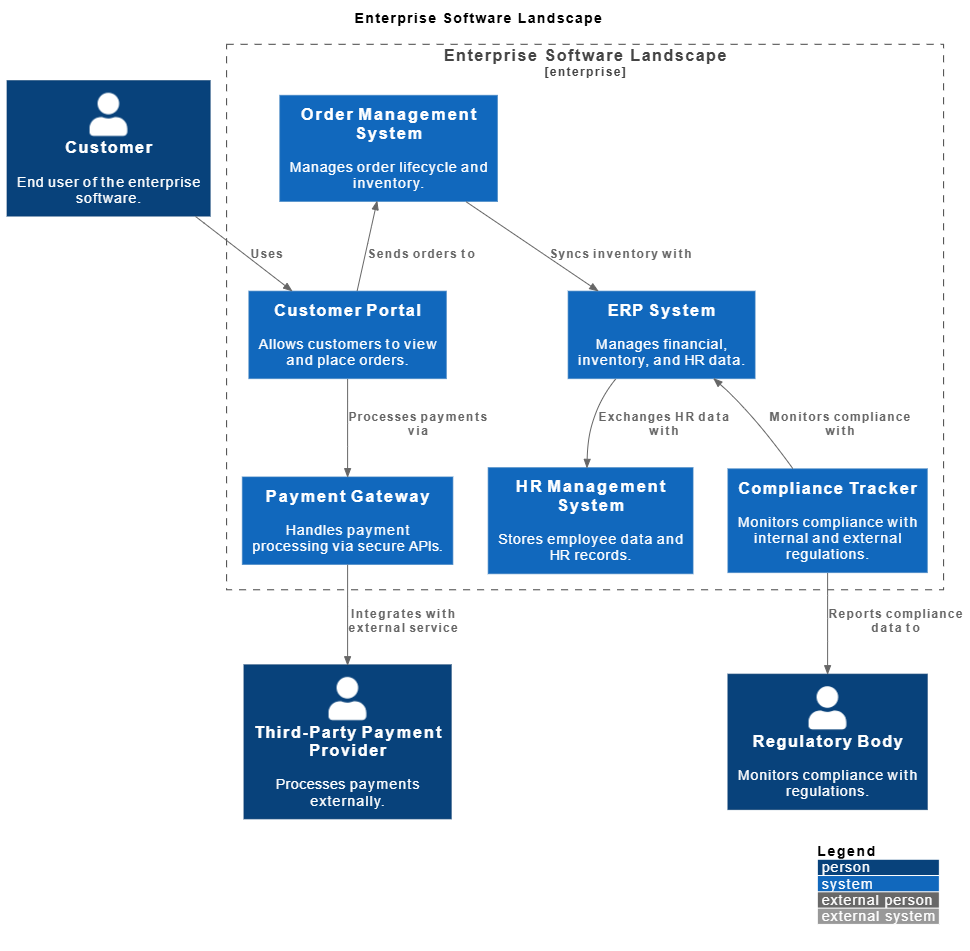
title Enterprise Software Landscape
Person(Customer, “Customer”, “End user of the enterprise software.”)
Person(RegBody, “Regulatory Body”, “Monitors compliance with regulations.”)
Person(PayProvider, “Third-Party Payment Provider”, “Processes payments externally.”)
Enterprise_Boundary(enterprise_software, “Enterprise Software Landscape”) {
System(CustomerPortal, “Customer Portal”, “Allows customers to view and place orders.”)
System(OrderMgmt, “Order Management System”, “Manages order lifecycle and inventory.”)
System(ERP, “ERP System”, “Manages financial, inventory, and HR data.”)
System(HRMS, “HR Management System”, “Stores employee data and HR records.”)
System(PayGateway, “Payment Gateway”, “Handles payment processing via secure APIs.”)
System(ComplianceTracker, “Compliance Tracker”, “Monitors compliance with internal and external regulations.”)
}
Rel(Customer, CustomerPortal, “Uses”)
Rel(CustomerPortal, OrderMgmt, “Sends orders to”)
Rel(OrderMgmt, ERP, “Syncs inventory with”)
Rel(ERP, HRMS, “Exchanges HR data with”)
Rel(CustomerPortal, PayGateway, “Processes payments via”)
Rel(PayGateway, PayProvider, “Integrates with external service”)
Rel(ComplianceTracker, ERP, “Monitors compliance with”)
Rel(ComplianceTracker, RegBody, “Reports compliance data to”)
Lay_D(PayProvider, PayGateway)
Lay_U(ComplianceTracker, ERP)
Lay_D(OrderMgmt, CustomerPortal)
@enduml
Visual Paradigm AI ChatBot Generated System Landscape Diagram
✅ Tip: Use
!includeurlto import the C4-PlantUML standard library for consistent styling.
✅ Step 7: Validate and Finalize
Before finalizing, perform the following checks:
-
Are all major enterprise systems included?
-
Are external dependencies clearly marked?
-
Are actors and systems correctly categorized (internal vs. external)?
-
Do relationships reflect real-world interactions?
-
Is the diagram readable and scalable?
⚠️ Warning: AI may misinterpret ambiguous terms (e.g., “CRM” could mean internal or external). Always verify context.
🔷 How the System Landscape Fits into the C4 Model Hierarchy
The C4 Model is structured in four progressive levels. The System Landscape is the starting point — Level 0 — and enables contextual understanding before diving deeper.
| C4 Level | Name | Scope | Purpose |
|---|---|---|---|
| Level 0 | System Landscape | Enterprise/Organization | Maps the entire portfolio of systems and their interactions. |
| Level 1 | System Context | Single System | Zooms into one system; shows users and external dependencies. |
| Level 2 | Container | Internal Structure | Breaks down a system into major technical components (e.g., web app, database, microservice). |
| Level 3 | Component | Detailed Module | Shows internal components and their relationships within a container. |
🔗 Key Relationship:
The System Landscape provides the context for System Context diagrams.
It helps architects and stakeholders identify which system to analyze next, ensuring that architectural decisions are made with full awareness of the enterprise landscape.
🔷 Best Practices for Effective System Landscape Diagrams
-
Keep It High-Level: Avoid naming individual microservices or databases. Focus on major systems.
-
Use Clear Labels: Name systems descriptively (e.g., “Customer Order Management System”, not “System-01”).
-
Categorize Systems: Use color or shape to distinguish:
-
Internal systems (e.g., blue)
-
External systems (e.g., red)
-
Third-party services (e.g., orange)
-
-
Minimize Clutter: Limit relationships to key interactions. Use “other” or “etc.” only if necessary.
-
Update Regularly: Treat the landscape as a living document — update it with new systems or decommissioned ones.
🔷 Common Pitfalls and How to Avoid Them
| Pitfall | Solution |
|---|---|
| AI generates irrelevant or fictional systems | Review output and remove or rename incorrect entries. |
| Overloading the diagram with too many systems | Focus on strategic systems; exclude minor or legacy tools unless critical. |
| Mislabeling internal vs. external systems | Use clear naming conventions and color coding. |
| Ignoring external dependencies | Ensure all third-party integrations (e.g., payment gateways, cloud services) are visible. |
🔷 Conclusion
Creating a C4 System Landscape Diagram in Visual Paradigm using the AI-powered C4 Model Generator is a fast, efficient, and scalable way to document your enterprise’s software portfolio. By combining natural language input with visual refinement, teams can quickly establish a shared understanding of the organization’s digital ecosystem.
This foundational diagram sets the stage for deeper architectural exploration, ensuring that every System Context, Container, and Component diagram is built on a solid, enterprise-wide context.
✅ Final Tip: Share the landscape diagram with stakeholders — product managers, CTOs, auditors, and developers — to align on system boundaries and dependencies.
📚 Reference List (Markdown Format)
- Visual Paradigm AI Diagram Generator: Complete C4 Model Support: This release notes highlight the integration of AI-powered C4 model generation, including support for System Landscape, Context, Container, and Component diagrams, enabling faster and smarter architecture documentation.
- About the C4 Diagrams in AI-Powered C4 PlantUML Studio: A comprehensive overview of how AI generates C4 diagrams, including guidance on input prompts, output validation, and use cases across enterprise architecture.
- AI C4 System Landscape Diagram Generator – Visual Paradigm Guide: A step-by-step tutorial on using Visual Paradigm’s AI tool to generate a System Landscape diagram from a natural language description.
- Visual Paradigm C4 PlantUML Studio Features: Official feature page detailing the full capabilities of C4 PlantUML Studio, including AI generation, PlantUML integration, and multi-level diagram support.
- Beginner’s Guide to C4 Model Diagrams: An accessible introduction to the C4 Model, explaining each level and how to use diagrams effectively in software architecture communication.
- The Ultimate Guide to C4 PlantUML Studio – Revolutionizing Software Architecture Design: A deep dive into how C4 PlantUML Studio, with AI assistance, transforms architecture design workflows for teams of all sizes.
- C4 Component Diagram: A Definitive Guide to Your Code’s Internal Structure: While focused on Level 3, this article reinforces the importance of the hierarchical structure starting from the Landscape diagram.
✅ Note: Always double-check AI-generated diagrams for accuracy, especially when used in compliance, audit, or strategic planning contexts. The AI is a powerful assistant — but human oversight ensures quality and correctness.
