


In modern software development, visual modeling plays a critical role in designing complex systems. Among the most powerful UML diagrams is the state diagram, which captures the dynamic behavior of a system by illustrating how it transitions between various states in response to events. With the rise of artificial intelligence in development tools, creating accurate and professional state diagrams has never been easier.
Core States & Transitions
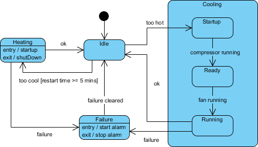
- Initial State: The black dot at the top indicates the system starts and immediately enters the Idle state.
- Idle: The default state. From here, the system can transition to:
- Heating: Triggered by the event
too cool, provided the guard condition[restart time >= 5 mins]is met. - Cooling (Composite State): Triggered by the event
too hot.
- Heating: Triggered by the event
- Heating: When entering this state, it executes
entry / startup. When leaving (via theokevent back to Idle), it executesexit / shutDown. - Cooling: This is a composite state containing its own internal workflow:
- Startup $\rightarrow$ Ready (triggered by
compressor running) - Ready $\rightarrow$ Running (triggered by
fan running) - From Running, the system can return to Idle via the
okevent.
- Startup $\rightarrow$ Ready (triggered by
- Failure: A safety state reachable from Heating, Idle, or Cooling via a
failureevent.- Actions: It triggers
entry / start alarmandexit / stop alarm. - Recovery: The system returns to Idle once the
failure clearedevent occurs.
- Actions: It triggers
UML State Diagram Tooling
Visual Paradigm, a leading UML modeling tool, integrates an intelligent AI Chatbot that streamlines the creation and refinement of state diagrams using natural language. This article walks you through the entire process—from launching the AI assistant to generating, refining, and even exporting code from your state machine diagram—ensuring efficiency, accuracy, and clarity.
🚀 Step 1: Initialize Your Project and AI Assistant
Before diving into diagram creation, set up your environment:
1. Launch Visual Paradigm
-
Open the Visual Paradigm desktop application or access the online version via https://online.visual-paradigm.com.
-
Create a new project or open an existing one where you want to build your state diagram.
2. Access the AI Assistant
-
Locate the AI icon in the top-right corner of the interface (a chat bubble).
-
Click it to open the AI Chatbot sidebar.
3. Start the Diagramming Process
Enter a clear, descriptive prompt to initiate diagram generation. For example:
“Create a state diagram for an ATM system.”
The AI will interpret your request and begin constructing a foundational state diagram based on common behaviors of an ATM, such as:
-
Idle
-
Inserting Card
-
Validating Card
-
Selecting Transaction
-
Processing Transaction
-
Dispensing Cash
-
Returning Card
-
Error States
✅ Pro Tip: Use specific, action-oriented language. Instead of “ATM system,” try:
“Create a state diagram for an ATM that detects card insertion, validates credentials, processes withdrawals, handles errors, and returns the card.”
This specificity leads to more accurate initial outputs.
🧠 Step 2: Generate and Refine with AI (Conversational Editing)
Once the AI generates the initial diagram, use natural language commands to iteratively refine it—no coding required.
🔹 Initial Generation
The AI returns a basic but functional state diagram with:
-
Start state (initial node)
-
Core states (e.g.,
Idle,Card Inserted,Processing,Error) -
Transitions labeled with events (e.g., “Card Inserted”, “Validated”, “Withdrawal Requested”)
-
Final state (e.g.,
Card Returned)
🔹 Conversational Editing: Add, Rename, and Modify
Engage in a back-and-forth conversation with the AI to enhance the model:
Add New States
“Add a ‘Card Blocked’ state after ‘Invalid Card’.”
Modify Transitions
“Add a transition from ‘Error’ back to ‘Idle’ when the user presses ‘Cancel’.”
Rename States for Clarity
“Rename ‘State1’ to ‘Payment Processing’.”
Introduce Composite States (Advanced)
For complex systems, ask for nested or composite states:
“Make ‘Transaction Processing’ a composite state with sub-states: ‘Validating Funds’, ‘Withdrawing Cash’, and ‘Confirming Transaction’.”
This improves readability and models hierarchical behavior effectively.
🔹 Iterate Until Accuracy Is Achieved
Use the “Compare with Previous” button in the AI chat window to review changes between iterations. This feature helps you track modifications and ensures you don’t lose important logic during refinement.
🔄 Example Workflow:
Prompt: “Create a state diagram for a checkout system.”
AI generates:
Idle → Cart Added → Payment → Success/FailureYou respond: “Add a ‘Pending’ state between ‘Cart Added’ and ‘Payment’.”
AI updates: Now includes
Pendingwith transition “Payment Initiated”You refine: “Add a guard condition: ‘if balance > 0’ on the transition from ‘Pending’ to ‘Payment’.”
Repeat until the diagram reflects your system’s real-world logic.
🛠️ Step 3: Import and Finalize in Visual Paradigm
Once satisfied with the AI-generated model, bring it into the full Visual Paradigm editor for final touches.
1. Import the Diagram
-
In the AI chat window, click “Import to Visual Paradigm”.
-
The diagram appears in your workspace as a fully editable UML state diagram.
2. Refine Visually
Use the standard Visual Paradigm interface to:
-
Rearrange nodes for better layout (drag-and-drop).
-
Align states and transitions for visual clarity.
-
Adjust colors, fonts, and styles to match your documentation standards.
3. Add Advanced Details
Enhance the diagram with professional UML elements:
-
Triggers: Events that cause transitions (e.g.,
Card Inserted,Timeout). -
Actions: Operations performed during transition (e.g.,
Log transaction,Eject card). -
Guard Conditions: Boolean expressions that must be true for a transition (e.g.,
if balance >= amount). -
Entry/Exit Actions: Define behavior when entering or exiting a state.
💡 Example:
Transition fromProcessing→Success
Trigger:
Transaction CompleteGuard:
amount <= availableBalanceAction:
Update account balance, Print receipt
These details make your diagram not just visual—but executable.
4. Generate Code Automatically
One of the most powerful features of Visual Paradigm is code generation from UML diagrams.
To generate code:
-
Select your state diagram.
-
Go to Tools > Code > Generate State Machine Code.
-
Choose your target language: Java, C#, Python, JavaScript, or others.
-
Click Generate.
The tool outputs clean, structured code that implements the state machine logic—perfect for integration into your application.
✅ Benefits:
Eliminates boilerplate code.
Ensures consistency between design and implementation.
Accelerates development cycles.
🎯 Tips for Better Results with Visual Paradigm’s AI
To maximize the effectiveness of the AI assistant, follow these best practices:
| Tip | Why It Matters |
|---|---|
| Use Specific Prompts | Vague prompts lead to generic diagrams. Include verbs like “detects”, “processes”, “fails”, “validates” to guide AI. |
| Leverage Composite States | For systems with layered logic (e.g., a payment gateway), ask the AI to create nested states for clarity. |
| Compare Versions | Use the “Compare with Previous” button to audit changes and avoid accidental overwrites. |
| Review AI Output Carefully | AI can hallucinate or misinterpret intent. Always validate states, transitions, and guards. |
| Combine AI with Manual Editing | Use AI for rapid prototyping, then refine manually for precision and compliance. |
📌 Conclusion: The Future of UML Modeling is AI-Powered
Visual Paradigm’s AI Chatbot transforms state diagram creation from a time-consuming, manual task into an intuitive, conversational experience. By combining natural language input with powerful modeling tools, developers and designers can:
-
Rapidly prototype system behavior.
-
Collaborate more effectively with stakeholders.
-
Reduce errors and inconsistencies.
-
Accelerate the path from design to deployment.
Whether you’re modeling an ATM, checkout system, IoT device, or automated toll gate, Visual Paradigm’s AI-assisted state diagramming offers a seamless, intelligent workflow.
More Examples
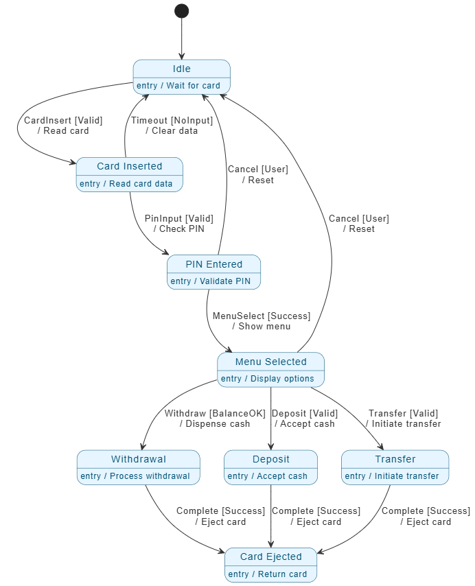
- Start & Idle: The system begins in the Idle state, waiting for a card.
- Authentication Path:
- Card Inserted: Triggered by a valid card. The system reads the data.
- PIN Entered: The user provides a PIN. If valid, the system moves forward; otherwise, a timeout or cancellation returns it to Idle.
- Transaction Selection:
- Menu Selected: Once authenticated, the user chooses an action.
- From here, the path splits into three main states: Withdrawal, Deposit, or Transfer.
- Each transition has a guard condition (e.g.,
[BalanceOK]) and an action (e.g.,/ Dispense cash).
- Completion:
- Once a transaction is successful, it moves to the Card Ejected state.
- The system then returns to the Idle state to wait for the next user.
- States (Blue Boxes): Represent the current condition of the ATM (e.g., “PIN Entered”).
- Transitions (Arrows): Show the movement between states triggered by events.
- Guard Conditions
[...]: Logic that must be true for the transition to happen (e.g., checking if there is enough money). - Actions
/ ...: Tasks the system performs during a transition (e.g., ejecting the card).
PlantUML
@startuml
skinparam shadowing false
skinparam {
‘ Colors
ArrowColor #333333
ArrowFontColor #333333
BackgroundColor #FFFFFF
BorderColor #333333
‘ State styling
State {
BorderColor #005073
BackgroundColor #E6F5FF
FontColor #005073
}
}
hide empty description
‘ — State Definitions (Use aliases for names with spaces/slashes) —
state “Idle” as Idle
Idle : entry / Wait for card
state “Card Inserted” as CardInserted
CardInserted : entry / Read card data
state “PIN Entered” as PinEntered
PinEntered : entry / Validate PIN
state “Menu Selected” as MenuSelected
MenuSelected : entry / Display options
state “Withdrawal” as Withdrawal
Withdrawal : entry / Process withdrawal
state “Deposit” as Deposit
Deposit : entry / Accept cash
state “Transfer” as Transfer
Transfer : entry / Initiate transfer
state “Card Ejected” as CardEjected
CardEjected : entry / Return card
‘ — Transitions (Use TechnicalIDs only) —
[*] –> Idle
Idle –> CardInserted : CardInsert [Valid]\n/ Read card
CardInserted –> PinEntered : PinInput [Valid]\n/ Check PIN
PinEntered –> MenuSelected : MenuSelect [Success]\n/ Show menu
MenuSelected –> Withdrawal : Withdraw [BalanceOK]\n/ Dispense cash
MenuSelected –> Deposit : Deposit [Valid]\n/ Accept cash
MenuSelected –> Transfer : Transfer [Valid]\n/ Initiate transfer
Withdrawal –> CardEjected : Complete [Success]\n/ Eject card
Deposit –> CardEjected : Complete [Success]\n/ Eject card
Transfer –> CardEjected : Complete [Success]\n/ Eject card
CardInserted –> Idle : Timeout [NoInput]\n/ Clear data
PinEntered –> Idle : Cancel [User]\n/ Reset
MenuSelected –> Idle : Cancel [User]\n/ Reset
@enduml
🔗 References & Further Reading
-
Mastering State Diagrams with Visual Paradigm AI – Cybermedian
-
Comprehensive Guide to UML State Machine Diagrams (Archimetric)
🧩 Final Thought
The fusion of AI and UML modeling is not just a trend—it’s a necessity in today’s agile, fast-paced development landscape. With Visual Paradigm’s AI Assistant, you’re not just drawing diagrams—you’re co-creating intelligent system models that evolve with your ideas.
Start small. Ask boldly. Iterate fast. And turn your vision into a working, documented, and deployable state machine—in minutes, not hours.
🌟 Ready to get started? Open Visual Paradigm, click the AI icon, and type:
“Create a state diagram for a smart thermostat that handles heating, cooling, and manual override.”
Your next state diagram is just one prompt away.
